7-30 - ATTACHMENTS/CONTROL LINKAGE 90-824052R3 JUNE 2002
Maintenance Instructions
Lubrication and maintenance inspection is owner’s
responsibility and must be performed at intervals
specified, following:
Normal Service - Every 50 hrs. of operation or 60
days (whichever comes first)
*Severe Service - Every 25 hrs. of operation or 30
days (whichever comes first)
*Operation in a salt water area is considered
“Severe Service.”
CAUTION
Core of steering cable must be fully retracted into
cable housing when lubricating cable. If cable is
lubricated while extended, hydraulic lock of
cable could occur.
1. Lubricate outboard end of RideGuide steering
cable (thru grease fitting - if equipped - next to
cable attaching nut) with Quicksilver 2-4-C
w/Teflon.
NOTE: RideGuide steering cable is lubricated at the
factory and requires no additional lubrication at initial
installation.
2. Lubricate all steering system pivot points (and
exposed portion of steering cable core) with
Quicksilver 2-4-C w/Teflon. Lubricate at intervals
specified preceding.
3. Carefully check steering system components for
wear (at intervals specified, preceding). Replace
worn parts.
4. Check steering system fasteners (at intervals
specified, preceding) to be sure that they are
torqued to correct specifications. (Figures 1, 2
and 3)
Clevis Attaching Kit
Installation (A-70599A2)
NOTE: This kit is used to attach RideGuide cable to
outboard steering arm ONLY when “Transom
Mounted RideGuide Attaching Kit” is being used.
If RideGuide cable is installed thru outboard tilt tube,
then “Steering Link Rod” must be used.
Installation Instructions
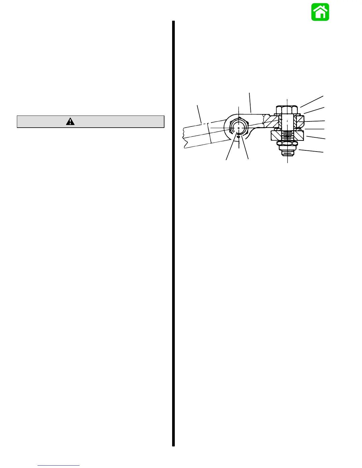
1. Install clevis to steering cable as shown.
2. Lubricate 3/8 in. x 1-3/8 in. (9.5 mm x 34.9 mm)
bolt (area without threads) with 2-4-C w/Teflon,
then secure clevis to steering cable with this bolt
and a locknut. Torque locknut (item “d”) to 10 Ib.
ft. (13.5 N·m).
b
a
e
f
g
h
i
j
d
c
a - Clevis
b - Steering Cable
c - Bolt [3/8 in. x 1-3/8 in. (9.5 mm x 34.9 mm)]
d - Clevis to Steering Cable Locknut [Torque to 10 lb. ft.
(13.5 N·m)]
e - Bolt [3/8 in. x 1-1/4 in. (9.5mm x 31.8mm)] [Torque to
20 lb. ft. (27.0 N·m)]
f - Thin Washer [1/16 in. (1.6mm) Thick]
g - Spacer
h - Thick Washer [1/8 in. (3.2mm) Thick]
i - Engine Steering Arm
j - Clevis to Engine Locknut [Torque to 20 lb. ft. (27.0 N·m)]
3. Lubricate spacer (supplied with this kit) with
2-4-C w/Teflon.
4. Attach clevis to top of outboard steering arm with
a 3/8 in. x 1-1/4 in. (9.5mm x 31.8mm) bolt, thin
washer, spacer, thick washer (thick washer must
be installed between clevis and steering arm)
and locknut, as shown. Torque bolt (item “e”) to
20 Ib. ft. (27.0 N·m), then torque locknut (item “j”)
to 20 Ib. ft. (27.0 N·m).

 Loading...