3D-68 - FUEL SYSTEMS 90-824052R3 JUNE 2002
6. Connect fuel inlet hose to vapor separator.
Secure hose with sta-strap.
7. Connect oil inlet hose to vapor separator. Secure
hose with sta-strap.
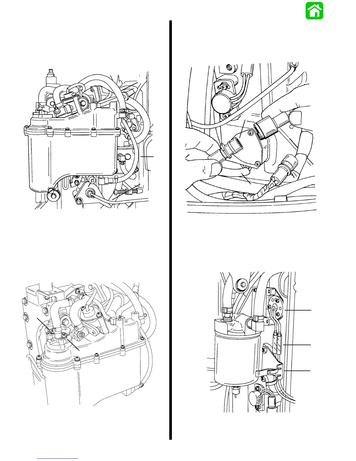
8. Install throttle link arm to throttle cam.
c
b
a
55203
a - Fuel Inlet Hose
b - Oil Inlet Hose
c - Throttle Link Arm
9. Connect RED (POSITIVE) lead to STARBOARD
terminal of electric fuel pump and BLACK/RED
(NEGATIVE) lead to PORT terminal of fuel pump.
Torque POSITIVE nut to 6 lb. in. (0.7 N·m) and the
NEGATIVE nut to 8 lb. in. (0.9 N·m).
a
b
55204
a - RED (+) Terminal [Torque nut to 6 lb. in. (0.7 N·m)]
b - BLACK/RED (–) Terminal [Torque nut to 8 lb. in. (0.9 N·m)]
Throttle Position Sensor, Air
Temperature Sensor and Fuel
Injector Harness Connections
1. Connect fuel injector harness at 4 pin connector.
a
b
51787
a - Injector Harness
b - 4 Pin Connector
2. Connect air temperature sensor leads to bullet
connectors. Position sensor leads behind har-
ness clamp.
55203
a
b
c
a - Air Temperature Sensor
b - Connectors
c - Harness Clamp

 Loading...