EasyManuals Logo

Mariner Mercury 135 JET User Manual

Mariner Mercury 135 JET
797 pages
To Next Page IconTo Next Page
To Previous Page IconTo Previous Page
Page #139 background imageLoading...
Page #139 background image
90-824052R3 JUNE 2002 ELECTRICAL - 2D-21
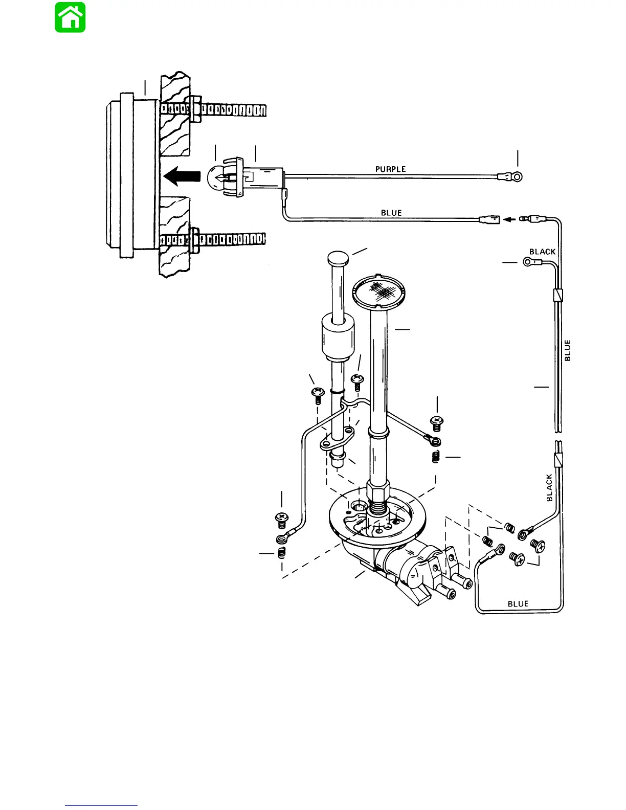
Visual Warning Wiring Diagram
1
2
3
4
5
6
7
7
8
9
10
11
12
8
10
8
13
14
10
1 - Bezel
2 - Lamp (GE #257)
3 - Socket Assembly
4 - Connect to Trim Indicator Gauge Terminal “I” or POSITIVE
(+) 12 Volt Source that is turned “ON” and “OFF” with
Ignition Switch.
5 - Connect to (–) NEGATIVE ground
6 - Float Tube Assembly
7 - Screw (Self Tapping) [5/8 in. (15.7mm) Long
8 - Screw [1/4 in. (6.3mm) Long
9 - Harness, 20 ft. (6m) Long
10- Spring
11- Retainer
12- O-Ring
13- Cap, Oil Tank
14- Oil Pickup Tube

Table of Contents

Questions and Answers:

Question and Answer IconNeed help?

Do you have a question about the Mariner Mercury 135 JET and is the answer not in the manual?

Mariner Mercury 135 JET Specifications

General IconGeneral
BrandMariner Mercury
Model135 JET
CategoryEngine
LanguageEnglish

Related product manuals