3E-10 - FUEL SYSTEMS 90-824052R3 JUNE 2002
Installing Drive Gear (for Oil Injection
Pump) Onto Crankshaft
IMPORTANT: Oil pump drive gear retaining
screws ARE STAKED after installation. DO NOT
remove drive gear from crankshaft unless gear is
damaged or shows signs of excessive wear.
REMOVAL OF DRIVE GEAR
1. Rotate crankshaft to gain access to two drive
gear retaining allen screws.
2. Remove two screws and remove drive gear from
crankshaft. DO NOT reuse retaining screws as
screw threads may be damaged by factory stak-
ing process.
b
a
c
51892
a - Retaining Nut
b - Allen Screw
c - Center Main Bearing (Hidden)
INSTALLATION OF NEW DRIVE GEAR
NOTE: If drive gear must be replaced, it is recom-
mended that the oil pump be inspected for operating
smoothness; plastic bearing, bronze bushing and oil
pump drive shaft be inspected for wear, gauling or
damage. Replace parts as required.
1. Align drive gear halves on crankshaft with retain-
ing screw access holes towards center main
bearing.
2. Clean retaining screw threads with Loctite Primer
T (92-59327-1). Apply Loctite 680 (obtain locally)
to screw threads.
3. Secure drive gear halves together with retaining
nuts and allen screws. Torque screws to 8 Ib. in.
(1.0 N·m).
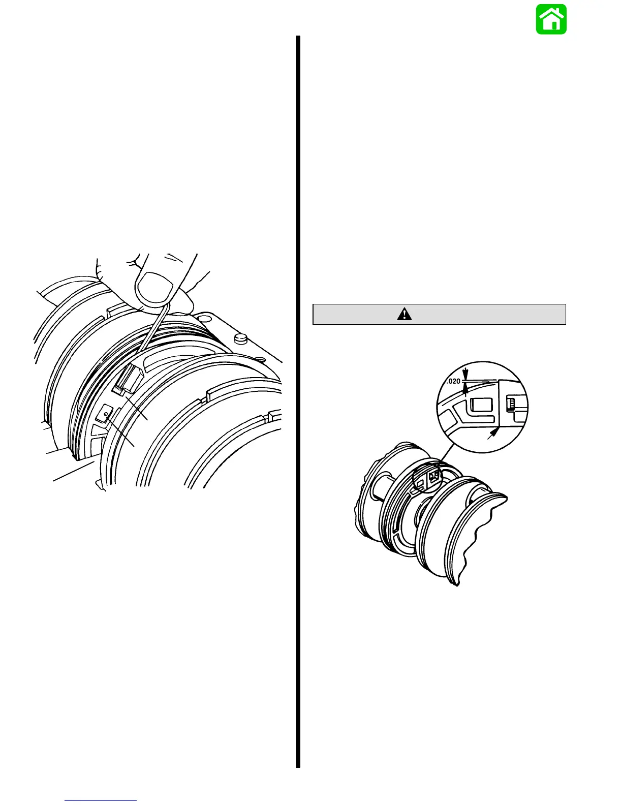
4. Check gear halve split lines. Split should be
drawn tight together (zero clearance) if gear
halves are properly installed.
CAUTION
Gear tooth mismatch at split line must not exceed
0.020 in. (0.50mm) or gear failure will result.
50755
Motion Sensor
Testing Procedure--Refer to “Oil Injection System
Trouble Shooting Chart,” following:
Removal--Remove screw securing sensor to oil
pump. Disconnect WHITE and BLUE/WHITE leads
from WARNING MODULE. Remove BLACK LEAD
from engine ground. Remove MOTION SENSOR
from powerhead.

 Loading...