ELECTRICAL - 2B-7
90-824052R3 JUNE 2002
VOLTAGE REGULATOR TEST
IMPORTANT: Make sure meter is “zeroed” by
shorting meter leads together after changing
selector knob to appropriate setting. The meter
reading must read “0” Ohms.
IMPORTANT: The following regulator tests
should be performed as soon as possible after
suspected regulator failure. A “cold” regulator
may test “GOOD” when in fact it is defective
when “warm”.
Disconnect all voltage regulator wires.
Voltage Regulator
Test
Using Analog
Meter
Test Leads To-
Resistance
(Ohms)
Scale
Diode Check: Con-
nect NEGATIVE (–)
ohm lead to either
YELLOW lead. Con-
nect POSITIVE (+)
test lead to thick
RED lead.
100-400 R x 10
Diode Check: Con-
nect NEGATIVE (–)
ohm lead to thick
RED lead. Connect
POSITIVE (+) ohm
lead to either YEL-
LOW lead.
20000 to ∞ R x 1K
SCR Checks: Con-
nect NEGATIVE (–)
ohm lead to either
YELLOW lead. Con-
nect POSITIVE (+)
ohm lead to case
ground.
8000 –
15000
R x 1K
Tachometer Circuit
Check: Connect
NEGATIVE (–) ohm
lead to case ground.
Connect POSITIVE
(+) ohm lead to
GRAY lead.
10000 –
50000
R x 1K
NOTE: Meters ground could be reversed for diode
test.
Voltage Regulator
Test
Using Digital Meter
Test Leads To-
Resistance
(Ohms)
Scale
Diode Check: Con-
nect NEGATIVE (–)
meter lead to RED
regulator lead in
connector. Connect
POSITIVE (+) test
lead to either YEL-
LOW regulator lead.
0.4 – 0.8
volts
Diode Check: Con-
nect NEGATIVE (–)
meter lead to either
YELLOW regulator
lead. Connect POS-
ITIVE (+) ohm lead
to RED regulator
lead in connector.
∞ or OUCH
or OL
SCR Checks: Con-
nect NEGATIVE (–)
meter lead to regu-
lator case. Connect
POSITIVE (+) meter
lead to either YEL-
LOW regulator lead.
1.5 volt – ∞
or OUCH or
OL
Tachometer Circuit
Check: Not measur-
able with digital me-
ter
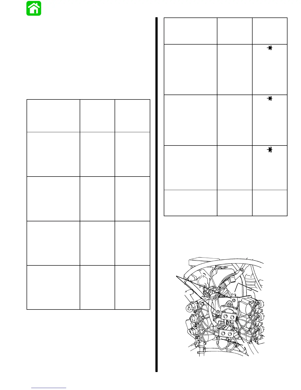
REMOVAL OF VOLTAGE REGULATORS
1. Remove 4 locknuts and spacers from coil mount-
ing plate. Lay coil mounting plate off to one side.
Production Models –
b
51797
a
a
a - 4 Locknuts
b - 4 Spacers (HIDDEN)

 Loading...