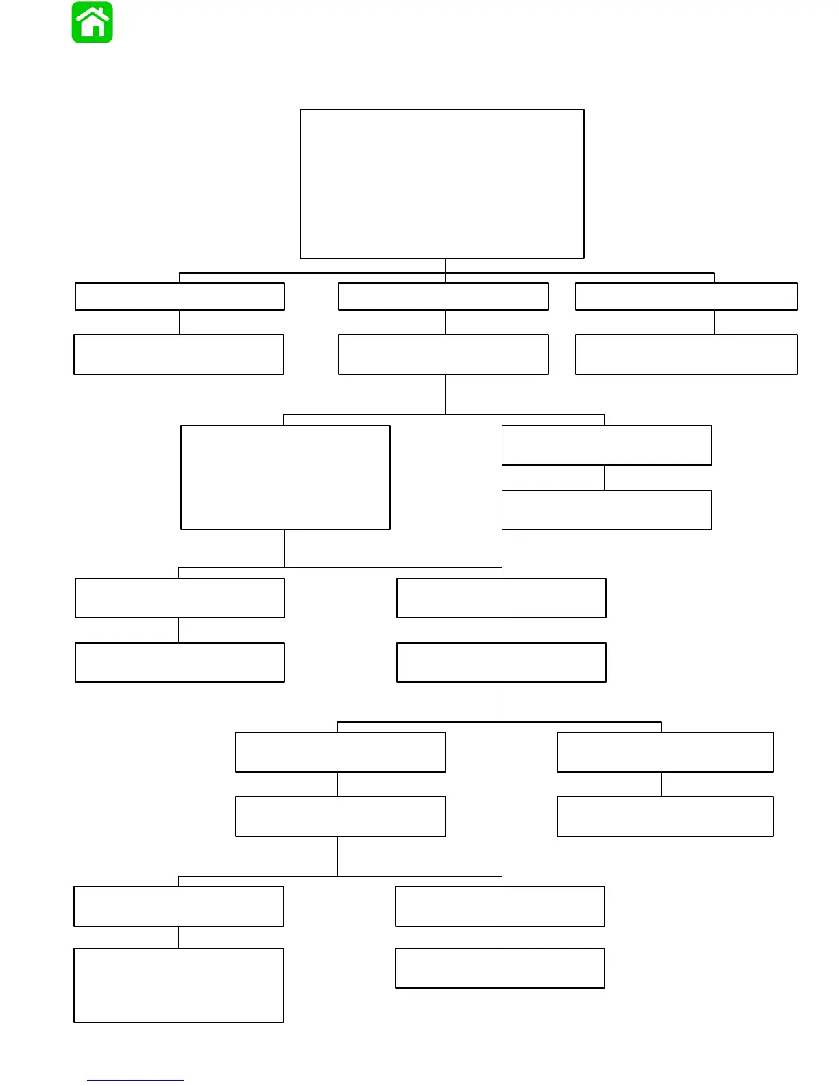
• Perform all preliminary checks 3D-13.
• Install fuel pressure gauge (P/N 91-16850A2)
on to manifold pressure port.
• Place ignition switch in “OFF” position 30 sec-
onds before testing.
• Place ignition switch in “ON” position and note
pressure within 30 seconds (34 to 36 psi; 234 to
248 kPa).
No or low fuel pressurePump does not run Fuel pressure above 36 psi (248 kPa)
Perform Vapor Separator Fuel
Delivery Test (page 3D-27).
Follow High Pressure Fuel
Route Flow Chart.
Follow High Pressure Fuel
Route Flow Chart.
No or little fuel flow from vapor
separator. Reconnect hose.
Fuel flows freely from vapor
separator. Reconnect hose.
Perform Vapor Separator Float
Test (page 3D-28).
Follow High Pressure Fuel
Route Flow Chart.
Fuel flows from fresh fuel inlet
hose.
Little or no flow from fresh fuel
inlet hose. Reconnect hose.
Inspect float system of vapor
separator.
Perform Water Separating Filter
Flow Test (page 3D-28).
Low or no fuel flow from water sep-
arating inlet hose. Reconnect hose.
Fuel flows freely from water separat-
ing filter inlet hose. Reconnect hose.
Perform Pulse Fuel Pump Deliv-
ery Test (page 3D-29).
Replace water separating
filter.
Fuel flows freely from pulse
pump inlet hose.
No fuel flow to pulse fuel
pump.
See pulse pump removal and
inspection section 3A. Locate all
fragments of failed pump before
reassembly.
Check for restrictions, holes or
loose connections from fuel supply.
Results Results
Results
Results
Results
Results
ResultsResults
Check in-line Filter
90-824052R3 JUNE 2002 FUEL SYSTEMS - 3D-23
EFI Fuel Management (Low Pressure Fuel Route)

 Loading...