90-824052R3 JUNE 2002 FUEL SYSTEMS - 3C-47
3. Install cover using screws.
b
a
51794
a - Cover
b - Screws
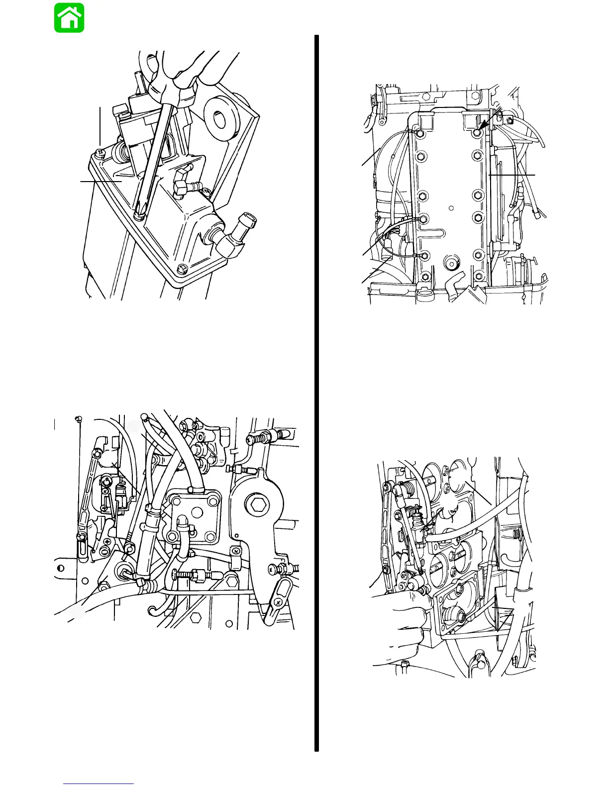
Manifold Removal
1. Disconnect throttle link rod from throttle cam.
2. Disconnect oil injection link rod from injector arm.
51811
d
c
b
a
a - Throttle Link Rod
b - Throttle Cam
c - Oil Injection Link Rod
d - Injector Arm
3. Identify location of 3 ground wires for reassembly
purposes.
4. Remove12 screws securing manifold cover to
manifold.
5. Remove manifold cover.
51795
a
a
a
c
b
a - Ground Wires
b - Screws (12)
c - Manifold Cover
6. Disconnect bleed line hose from bleed shut off.
7. Disconnect bleed line hoses from manifold
fittings.
8. Remove manifold assembly and place on clean
work surface.
51795
c
a
b
a - Bleed Hose
b - Bleed Shut Off
c - Bleed Hoses

 Loading...