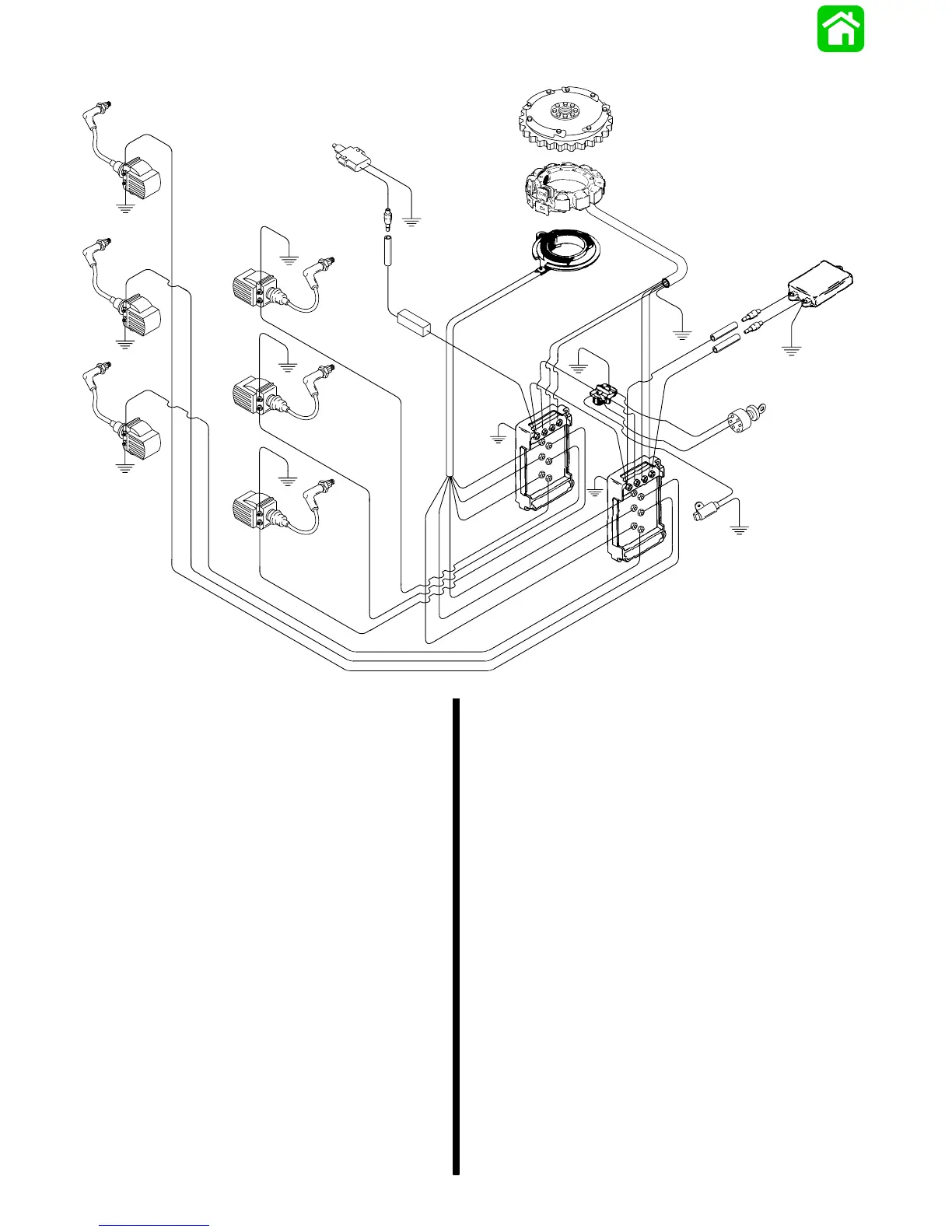
#2 Coil
#4 Coil
#6 Coil
#1 Coil
#3 Coil
#5 Coil
Flywheel
Stator
Trigger
Inner
Switch Box
Ignition Key Switch
Mercury
(Tilt)
Switch
Outer
Switch Box
Shift Interrupt Switch
Diode
Idle Stabilizer
2A-10 - ELECTRICAL 90-824052R3 JUNE 2002
Theory of Operation
Description
The V-6 outboard ignition system is alternator-driven
with distributor-less capacitor discharge. Major
components of the system are the flywheel, stator
assembly, trigger assembly, 2 switch boxes, 6
ignition coils and 6 spark plugs.
The stator assembly is mounted below the flywheel
and has 4 capacitor charging coils. The 4 capacitor
charging coils are composed of 2 high speed and 2
low speed coils-1 high speed and1 low speed coil for
each switch box. The low speed coils provide primary
voltage for the switch boxes from idle to approximate-
ly 2500 RPM. The high speed coils provide primary
voltage from 2000 RPM to the maximum RPM the
outboard is capable of achieving.
The flywheel is fitted with permanent magnets inside
the outer rim. As the flywheel rotates, the permanent
magnets pass the capacitor charging coils producing
AC voltage. The AC voltage is conducted to the
switch boxes where it is rectified and stored in a
capacitor.
The trigger assembly (also mounted under the fly-
wheel) has 3 coils. Each coil controls the spark to 2
cylinders -1 cylinder each bank. The flywheel also
has a second set of permanent magnets located
around the center hub. As the flywheel rotates, the
magnets pass the trigger coils producing AC voltage.
The AC voltage is conducted to an electronic switch
(SCR) in the switch box. The switch discharges the
capacitor voltage into the ignition coil at the correct
time and in firing order sequence.
Capacitor voltage is conducted to primary side of ig-
nition coil. As this voltage goes to ground through the
primary circuit of the coil, it induces a voltage rise in
the secondary side of the ignition coil. This voltage
can increase to approximately 40000 volts before
bridging the spark plug gap and returning to ground.
The preceding sequence occurs once per engine
revolution for each cylinder.
Spark timing is advanced or retarded by the move-
ment of the trigger assembly attached to the throttle/
spark arm.

 Loading...