2B-8 - ELECTRICAL 90-824052R3 JUNE 2002
Pro Max/Super Magnum Models –
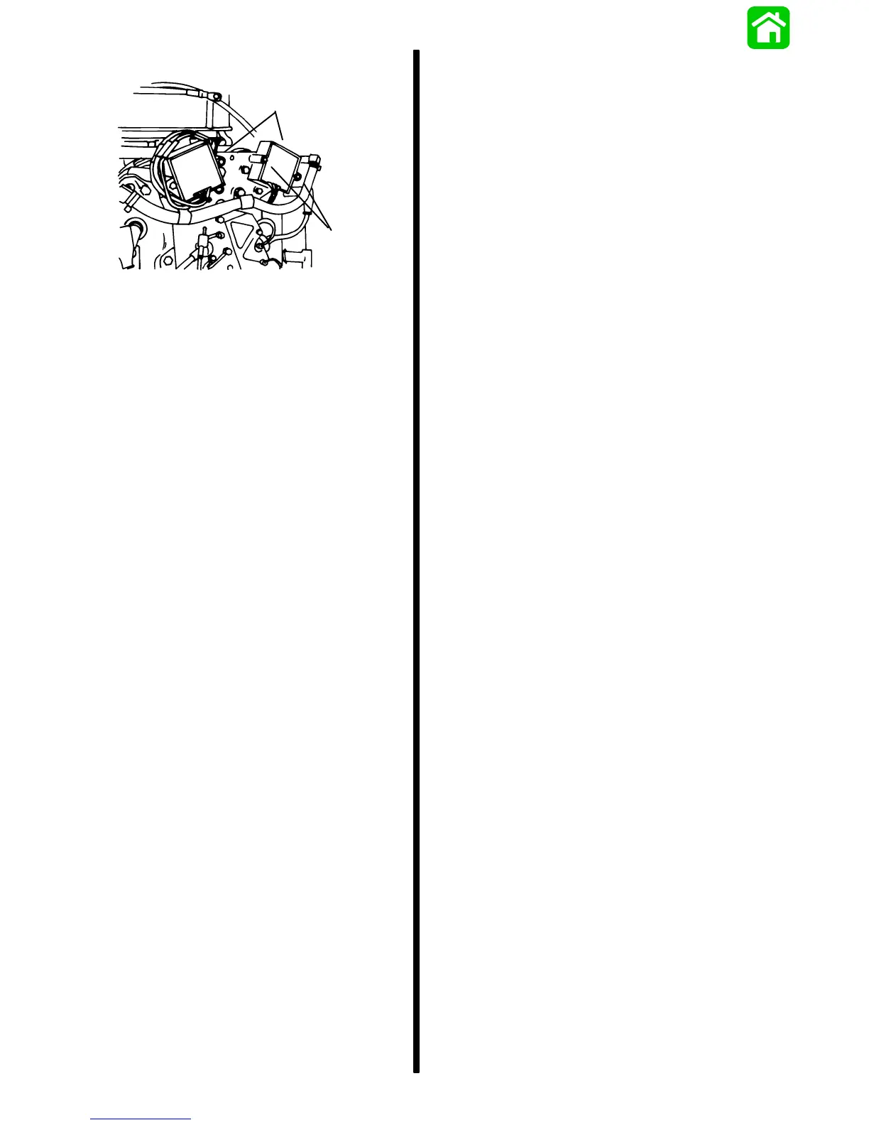
a
b
a - Regulators
b - Screws
2. Disconnect 2 YELLOW leads, 2 RED leads and
GRAY tach lead (if connected) from respective
bullet connectors.
3. Remove voltage regulator/rectifier from
powerhead.
INSTALLATION OF VOLTAGE REGULATOR/
RECTIFIER
1. Position regulators over attaching studs
(production models).
2. Connect YELLOW, RED and GRAY (as required)
leads to their respective bullet connectors.
3. Position spacers over attaching studs
(production models).
NOTE: Pro Max/Super Magnum regulators are
secured to powerhead with bolts and lock nuts.
4. Position coil/solenoid plate over attaching studs.
Place trim ground lead (BLACK) onto bottom
stud.
5. Secure plate, regulators and trim ground lead to
powerhead with locknuts. Torque nuts to 80 lb. in.
(9.0 N·m).

 Loading...