2D-24 - ELECTRICAL 90-824052R3 JUNE 2002
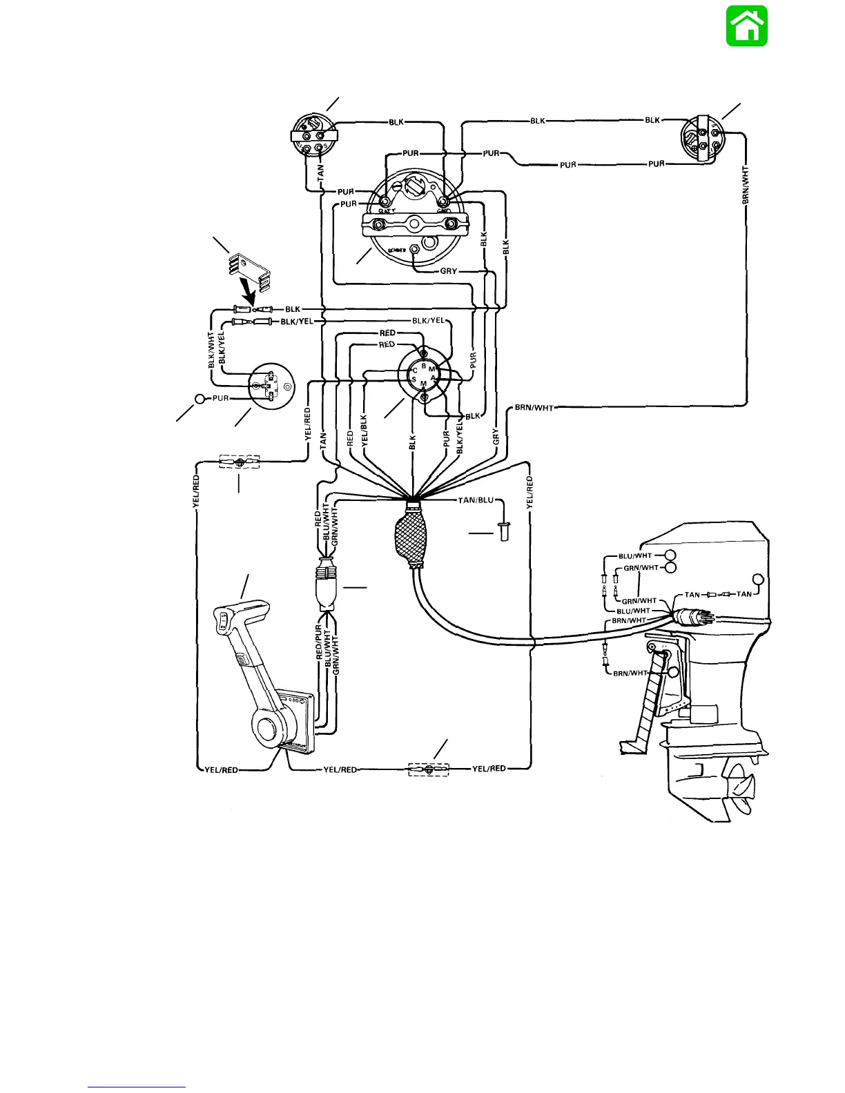
Instrument/Lanyard Stop Switch Wiring Diagram
BLK=BLACK
BLU=BLUE
BRN=BROWN
GRN=GREEN
GRY=GRAY
PUR=PURPLE
RED=RED
TAN=TAN
WHT=WHITE
YEL=YELLOW
52204
g
d
e
f
a
b
c
j
i
k
j
h
a - Ignition/Choke Switch
b - Lanyard Stop Switch
c - Lead Not Used on Outboard Installations
d - Retainer
e - Tachometer
f - Trim Indicator Gauge (Optional)
g - Temperature Gauge
h - Remote Control
i - Power Trim Harness Connector
j - Connect Wires Together w/Screw and Nut (2 Places); Ap-
ply Liquid Neoprene to Connections and Slide Rubber
Sleeve over each Connection.
k - Lead to Optional Visual Warning Kit

 Loading...