4A-56 - POWERHEAD 90-824052R3 JUNE 2002
19. Install shift cable assembly as shown Refer to
“Cable Adjustment” Section 7.
a
b
e
d
g
f
c
h
51853
a - Lock Nut
b - Shift Cable Latch
c - Flat Washer (Hidden)
d - Nylon Wear Plate
e - Spring (Hidden)
f - Shift Cable
g - Anchor Bracket
h - Throttle Cable
Refer to Section 2 of this Service Manual “Timing/
Synchronizing/Adjusting” for engine set-up
procedures.
IMPORTANT: E.F.I. POWERHEADS--
1. It is recommended that the bleed hose going to
the vapor separator be disconnected prior to the
bleed hose in-line filter. Place disconnected
bleed hose in a refuse container.
2. With engine on flush attachment or with boat in
water, start engine and run at 1500 RPM for
approximately 1/2 hour. This should remove any
debris from bleed system and prevent premature
clogging of bleed filter.
3. Stop engine. Re-connect bleed hose to bleed
filter. Discard flushed fluid in a correct waste
material handling facility.
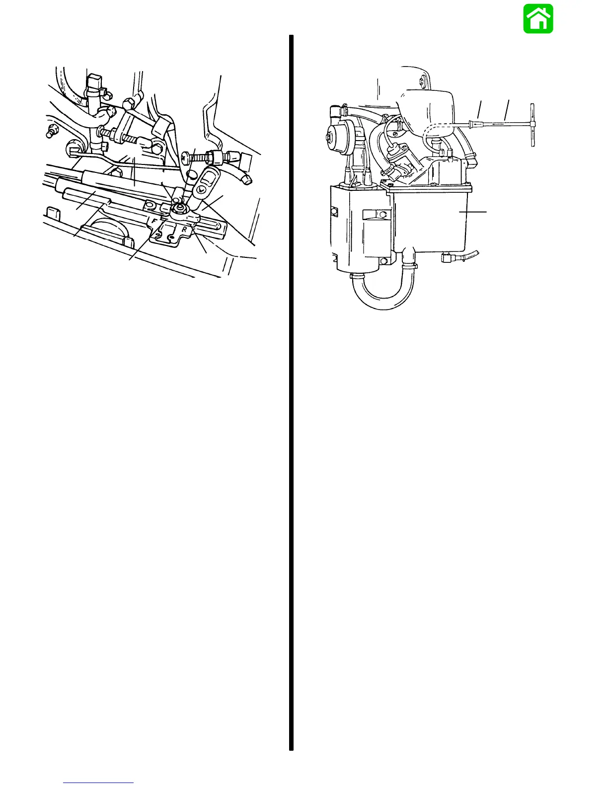
NOTE: Diagram shown without bleed shut-off valve
SN. 0G303046 and Above.
b
c
a
50345
a - Vapor Separator
b - Bleed Hose In-Line Filter
c - Bleed Hose

 Loading...