5B-18 - MID-SECTION 90-824052R3 JUNE 2002
NOTE: A small amount of trim fluid may drip from
manual release valve hole. Place a suitable contain-
er under trim assembly to collect any leakage.
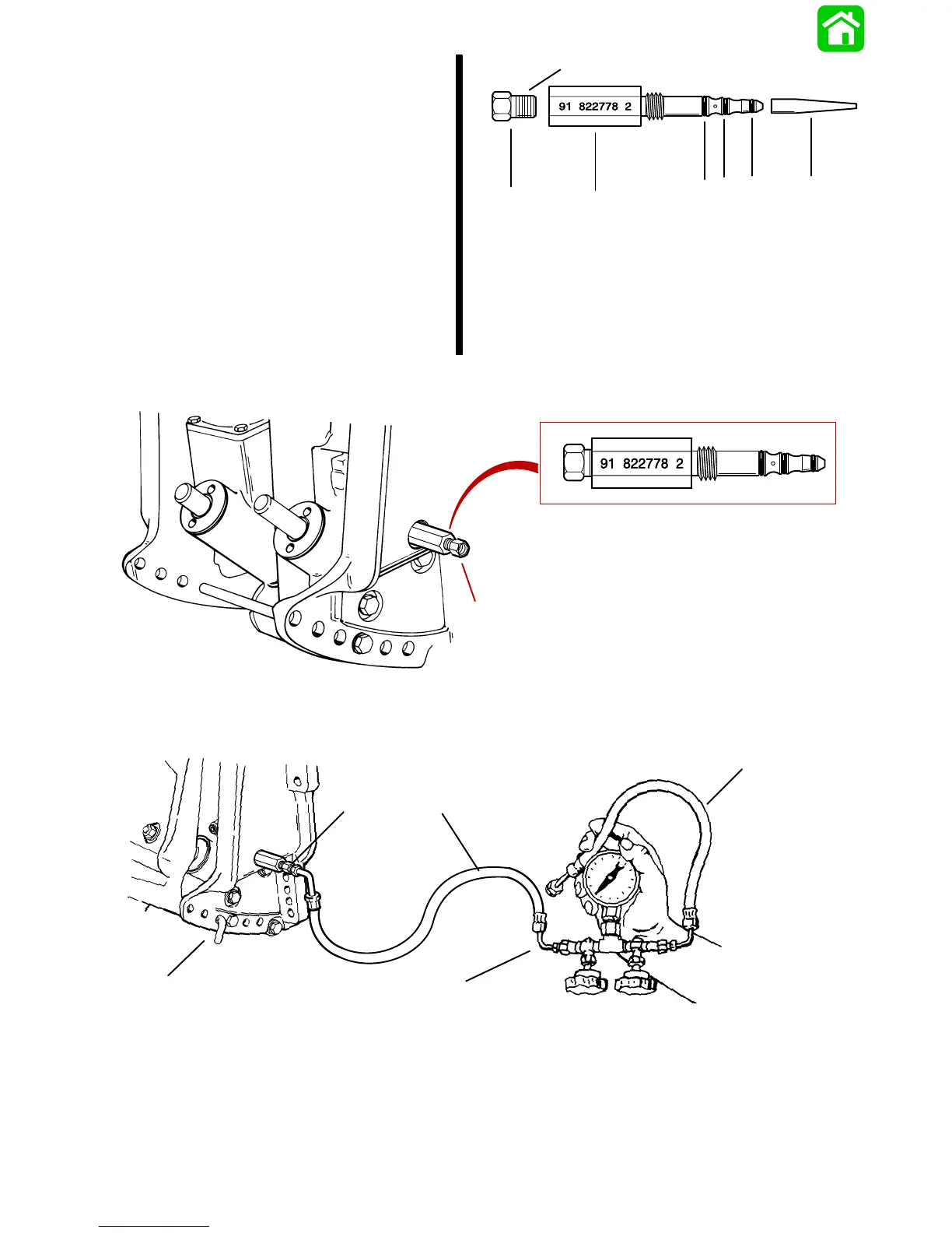
NOTE: Assemble test adaptor by using O-ring instal-
lation tool to position small O-ring onto adaptor 1st,
then install medium O-ring and lastly large O-ring.
Thread brass fitting into test adaptor securely using
teflon tape on threads.
f
e
d
cb
a
54457
g
a - Test Adaptor (91-822778A2)
b - O-ring Installation Tool
c - Small O-ring (Install 1st)
d - Medium O-ring (Install 2nd)
e - Large O-ring (Install Last)
f - Brass Fitting
g - Apply Teflon Tape
4. Install test adaptor 91-822778A2 into manual release valve hole.
54458
a
a - Test Adaptor (91-822778A2)
5. Thread hose from Test Gauge Kit (91-52915A6) into brass fitting on adaptor.
54459
e
b
d
c
a
a - Brass Fitting
b - Test Gauge Assembly
c - Tilt Pin (Position in Hole Shown)
d - Hose
e - Hose (Not Used)

 Loading...