6F-10 - JET OUTBOARDS 90-824052R3 JUNE 2002
INSTALLATION
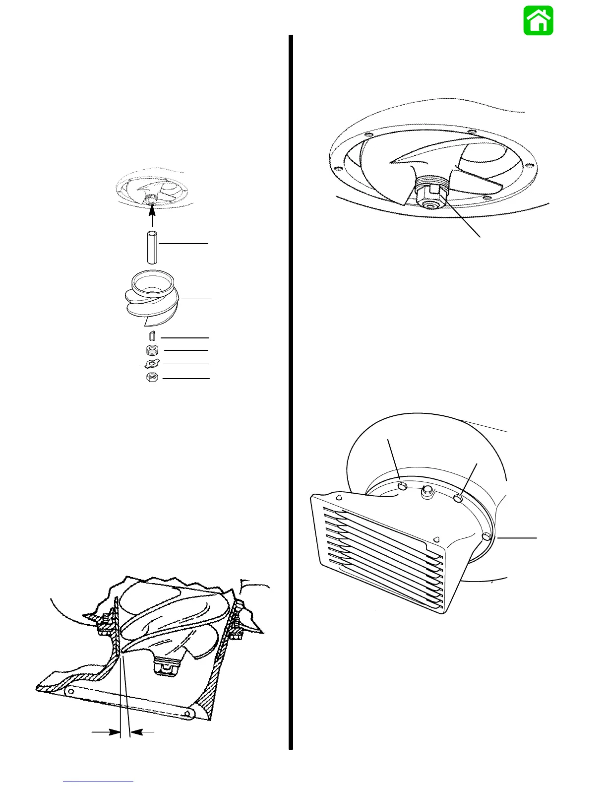
1. Grease the driveshaft, shear key, and impeller
bore. Place the plastic sleeve (a) inside the
impeller (b) and install impeller, shear key (c),
shims (d) tab washer (e), and impeller nut (f).
Turn the nut tight on the shaft to remove any play
between the impeller and shaft. If the tabs on the
retainer do not line up with the flats on the nut,
remove the nut and turn the retainer over and
re-tighten the nut again.
a
b
c
d
e
f
a - Plastic Sleeve
b - Impeller
c - Shear Key
d - Shims
e - Tab Washer
f - Impeller Nut
2. Temporarily reinstall the water intake housing in
order to check for impeller clearance. The
clearance between the impeller and liner should
be 0.030 in. (0.8 mm). Shim washers can be
transferred to either side of the impeller to raise
or lower the impeller to the correct clearance
setting. The water intake housing can be shifted
side ways a small amount in order to center the
liner.
.03 in. (.8mm)
3. After setting the impeller height, tighten the
impeller nut snug with a wrench. Secure impeller
nut by bending tabs (a) against the flats on the
impeller nut.
a
a - Tabs
4. Reinstall the water intake housing with six bolts.
Check clearance around the impeller to make
sure the water intake housing is centered and not
rubbing against the liner. Torque mounting bolts
to 100 lb. in. (11.0 N·m).
NOTE: If the outboard is used in salt water, apply
Quicksilver Anti-Corrosion Grease around the entire
mounting flange on the water intake housing and also
to the threads on the six mounting bolts.
a
a
a
a - Bolts [Torque bolts to 100 lb. in. (11.0 N·m)]

 Loading...