Motion control C3F_T40
260 192-121102 N04 June 2008
Decoupling with change-over function (CouplingMode = 2)
The standstill position is continually displayed during decoupling, while the curve is
continually hidden.
Overspeeding and pull-out movement are possible.
By the specification of the master-related decoupling and braking position in master
units, the decoupling curve is mapped on any length of the curve.
Algorithm of the change-over function
The normalized coupling function corresponds to the coupling function, but it is run
trough in inverse direction during decoupling. It provides factor KA, which is used
for the weighting.
The course of the decoupling curve depends on the standstill position and the
course of the curve in synchronized operation.
The weighting is made according to the following function:
decoupling curve = SK * KA + S0 * (1 – KA)
with:
S0 = standstill position
SK = current curve setpoint value
KA = control variable between 1.0 ... 0 (between MA and MB)
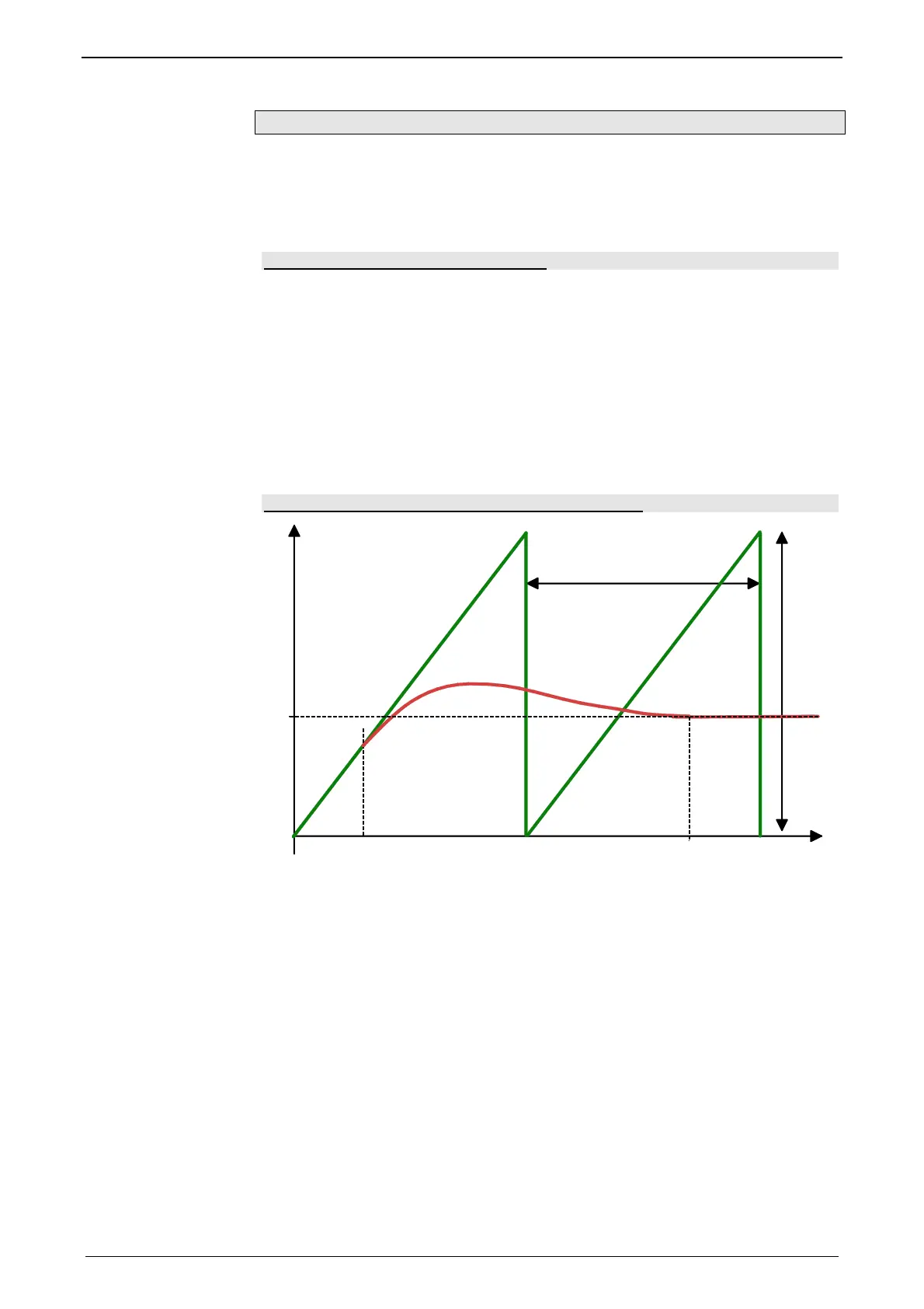
Example: Decoupling with the changeover-function
M
S
ST
MT
S0
MA
MB
0
S0: Slave standstill position
MA: Master decoupling position = 60°
MB: Master braking position 680°
MT: Master clock distance = 360°
ST: Slave clock distance

 Loading...


