Communication
C3F_T40
400 192-121102 N04 June 2008
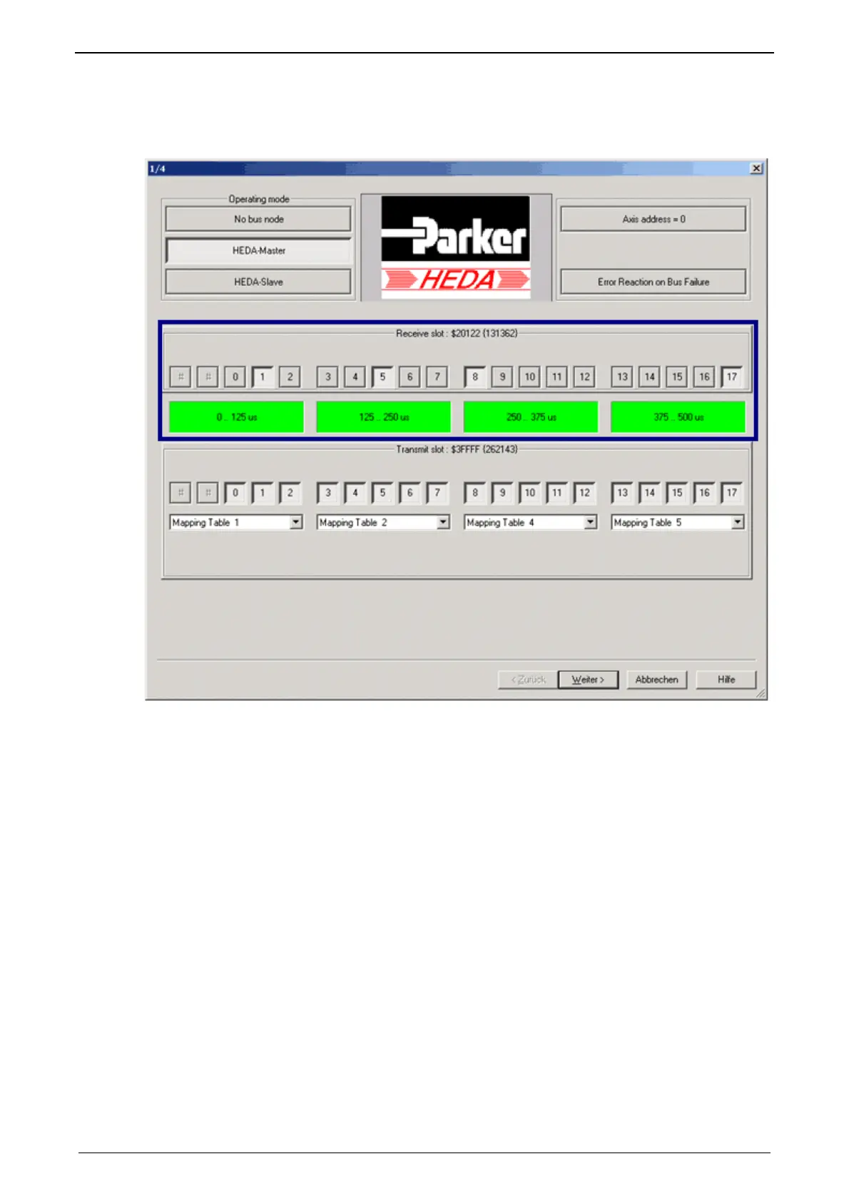
Master receive slots
Áctivate the receive slots from which the slave sends data (corresponding to the
settings in the slave).
In each of the 125µs cycles (slot 0...2, slot 3...7, slot 8...12, slot 13...17) data can
be received only via one slot, see also the
HEDA communication structure (see
page 396).
The assig
nment of the data is made via the mapping table number (which was
defined in the slave), this number is also received.
In the Wizard window "Receive Mapping table", it is defined under this mapping
table number where the data received are to be written to.
Master Transmit Mapping Table (max. 4)
Here the transmit mapping tables, which were assigned to the max. 4 transmit
125µs slots, are defined.
Procedure:
Selection of the corresponding transmit mapping table.
Selection of the Compax3 objects to be transmitted.
The assignment of the mapping table is permanently identified and displayed.
Up to 7 words are possible.
How many words are used by an object (see page 414) depends on the bus
format
(see page 363) / DSP format
For axis
coupling, please use the
coupling objects (see page 412) in the DSP
format
(see page 395) (selected by clicking on the DSP switch).
Please make sure that the DSP switch is activated on the master and the slave
side in DSP format.
Note:

 Loading...


