Setting up Compax3 C3F_T40
84 192-121102 N04 June 2008
Structure:
Master Z1 MasterPos Gearing numerator Slave - N2 Slave_U Load
N1 Gearing
denominator
Units Z2 to motor
Gearbox
Detailed structure image
with:
Z1
Travel Distance per Master Axis revolution
(M_Units/rev)
MD =
N1
*
Travel Distance per Master Axis revolution
- Denominator
Entry in the ”configuration
of the signal source” wizard
Z2
Travel path per revolution slave axis
numerator
SD =
N2
*
Travel path per revolution slave axis
denominator
Entry in the ”configuration
of the signal source”
wizard
MD:
Feed of the master axis
SD:
Feed of the slave axis
SSI configuration
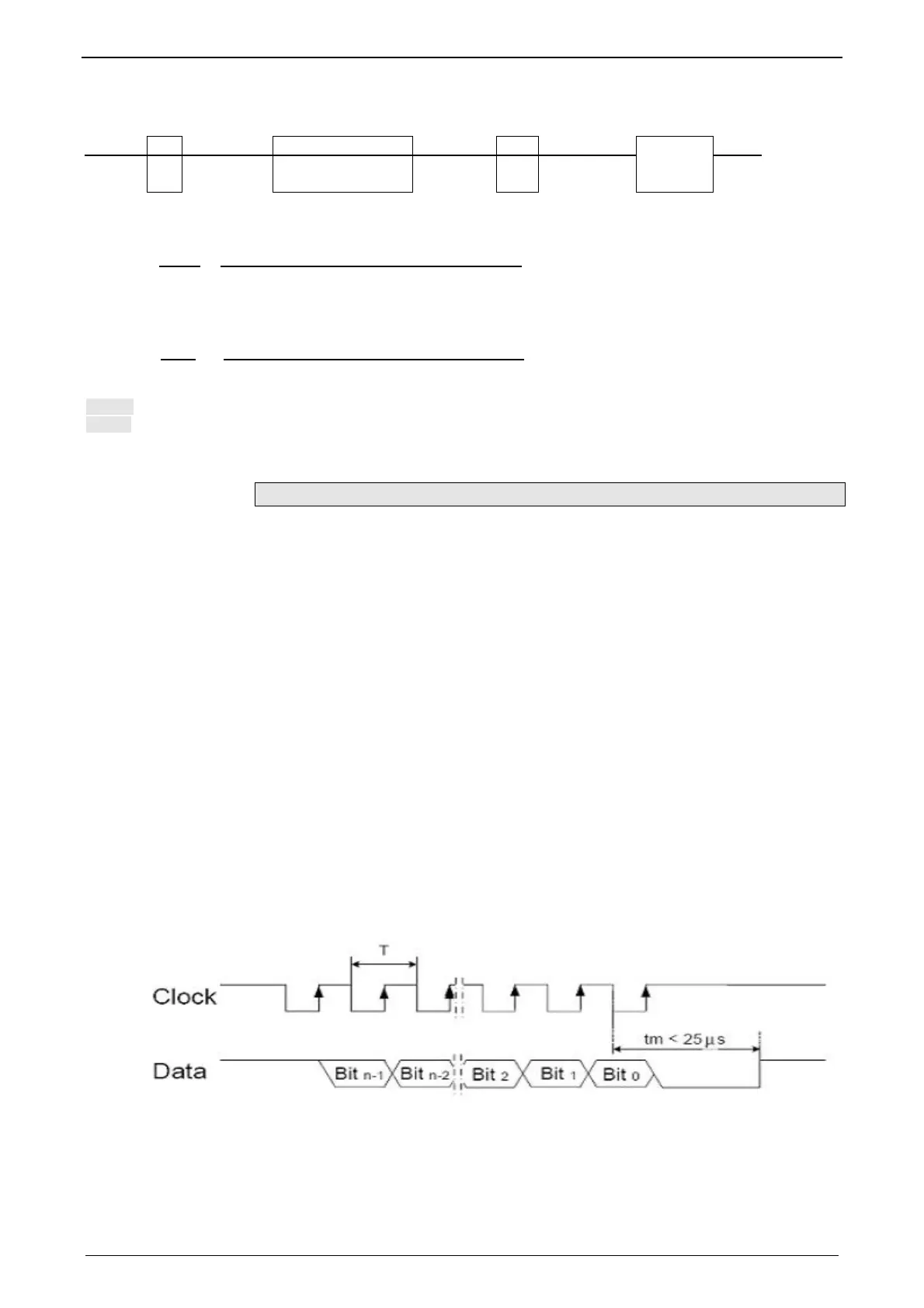
Notes on the SSI sensor (see page 84)
With Multiturn: Number of sensor rotations with absolute reference
Word length: Gives the telegram length of the sensor.
Baud rate/step: Max. transmission rate of the path measurement system.
Gray code: Sensor gray code coded yes/no (if no binary coded).
Note:
The absolute position is not evaluated!
It is available in the objects 680.24 (load position) and 680.25 (master position)
(C3T30, C3T40).
General requirements for supported SSI feedbacks
Baud rate: 350k ... 5MBaud
Word length: 8 ... 32 Bit
Binary or gray code (start value = 0)
Initialization time after PowerOn: < 1.1s
Signal layout:

 Loading...


