System Components
2-28 Hardware Description
• J3-J6: additional output receptacles that are either high or low voltage depending on
the position of switch S3
• S3: sets voltage output of J3-J6 high if set to 240/240-254/240/220-240 V~
sets voltage output of J3-J6 low if set to 120/120-127/120/110-120 V~
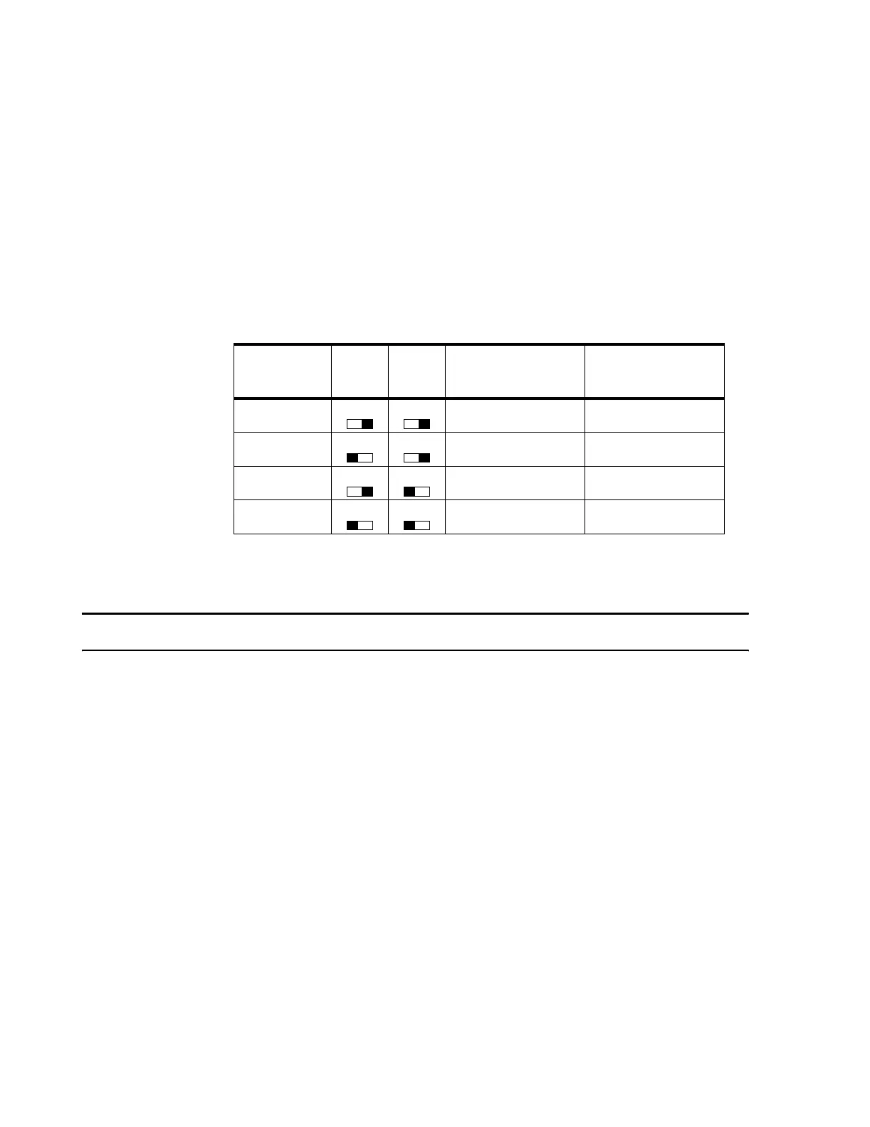
• S1 and S2: should be set to match the input voltage on receptacle P1 according to the
following table.
1
if S3 set to 240/240-254/240/220-240 V
AC
2
if S3 set to 120/120-127/240/110120 V
AC
Note The Input Voltage (P1) for Japanese installations is typically 100V.
A more detailed description of the Power Distribution Model is provided in the Power
Distribution Module Installation Note which is contained on the Documentation CD-
ROM.
Table 2-2. Input and Output Voltages for S1 & S2 Switch Settings
if
P1
Input Voltage
set
S2
set
S1
then
1
J1 & J3-J6
Output Voltage HIgh
or
2
J2 & J3-J6
Output Voltage Low
100 V 240 V 120 V
120 - 127 V 240 - 254 V 120 - 127 V
200 V 240 V 120 V
220 - 240 V 220 - 240 V 110 - 120 V
 Loading...