Locating System Components
Hardware Installation
5-11
Information
Center
Installation
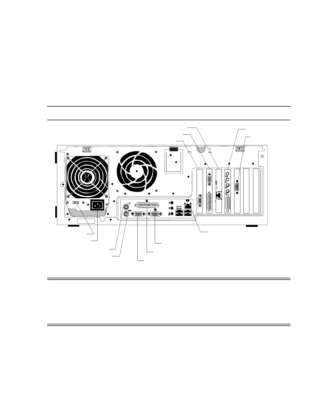
The final step is to install all Information Centers, Clients, and their peripheral equipment --
displays, keyboards, mouses, video splitters, keyboard-video-mouse switches, recorders, etc.
in their planned locations. Rear panel cabling connections for Information Center
workstations are shown in Figure 5-11. Rear panel cables without screw connected plugs
must also be secured so they do not accidentally unplug. Figure 5-13 shows examples of
how to secure cables of friction fit plugs to cables with screw connected plugs using cable
ties.
Note Connect the speaker to the connector on the Audio Card with the speaker icon.
.
Figure 5-11 Rear Panel Connections to D510 Information Center PC
Warning Cables with plugs not firmly attached by screw connections must be secured to prevent
accidental unplugging. Make certain that the speaker cable cannot accidentally be
pulled out because it annunciates alarms. Use the Strain Relief Kit (M3150-60019)
provided and secure the speaker cable to another cable that is secured with a screw
connection. When securing all cables, be sure to provide strain relief loops and cinch
cable ties securely. See Figure 5-13.
Step 1. Install the 650 VA UPS with the proper voltage for the PC as follows:
– Connect the battery wire of the 650 VA UPS.
– Turn Off the UPS On/Off switches.
– Connect the UPS input power cord to a properly grounded electrical output.
Power Cord Connector
Voltage Select Switch
Mouse Connector
Keyboard Connector
First Serial Connector (COM A)
Display Connector (not used if Dual Display)
Parallel Connector
Sound Card
Dual Video Card
SDN Card
Second Serial
Connector (COM B)
(Optional)
LAN Connector
10BT
100TX
-
(Optional) Hospital LAN NIC Card
 Loading...