Overview
5-2 Hardware Installation
The noise immunity of fiber optic cable is superior to UTP cable so that fiber optic cable
should be used for any 10 Mbit/s cable runs over 100 m for which RF or electrical noise is
a potential problem.
UTP Cable Plant
Installation
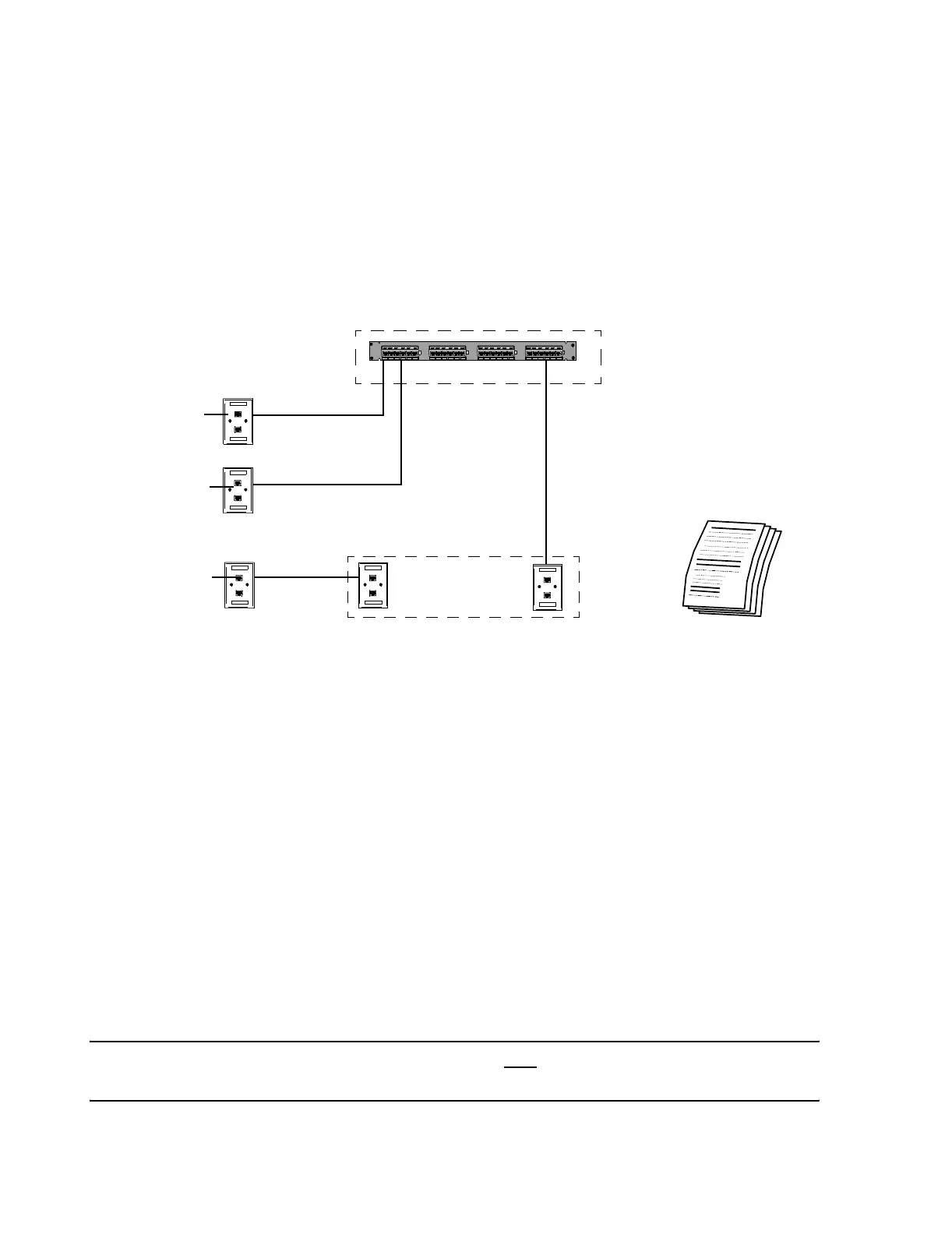
A typical cable plant installation for UTP Category 5 cables for Information Centers,
Clients and Clinical Network/Database Server components is shown in Figure 5-1.
Figure 5-1 Typical UTP CAT5 Cable Plant Installation
The UTP CAT5 cable plant should meet the following:
• Patch panels for all switches should be in the wiring closets where switches will be
installed
• RJ-45 wall boxes or patch panels for repeaters and extension switches should be
in closets where they will be installed. Repeaters and Extension Switches should not
be located above a ceiling.
• RJ-45 Wall boxes for Information Centers, Clients, Printers, and Server, should
be within patch cable lengths of their devices.
• Cabling, patch panels, switches, repeaters, and media translators should be more
than 1 m (3 ft.) from all powered devices (Server, UPS, etc.).
• Labels on all UTP CAT5 cables and terminations should identify the cable, patch
panel, port number, and wall box termination.
• Test Documentation should demonstrate that the UTP CAT5 cable plant meets
CAT5 standards for NEXT, attenuation, wiremap, and length.
Caution In-wall cabling - UTP and fiber optic - must
be terminated at a patch panel or wall
box and not directly at an active Network device.
Wiring Closet for DBS
Wiring Closet for Repeater
Test Documentation
Patch Panel
CATEGORY 5
CATEGORY 5
262-1
262-1
CATEGORY 5
CATEGORY 5
262-1
262-1
CATEGORY 5
CATEGORY 5
262-1
262-1
CATEGORY 5
CATEGORY 5
262-1
262-1
CATEGORY 5
CATEGORY 5
262-1
262-1
12
3
45 6
789101112 13 14 15 16 17 18 19 20 21 22 23 24
AMP
Information
Center
Client
Information
Center
Printer
 Loading...