Interconnecting the System
Hardware Installation
5-19
Interconnecting the System
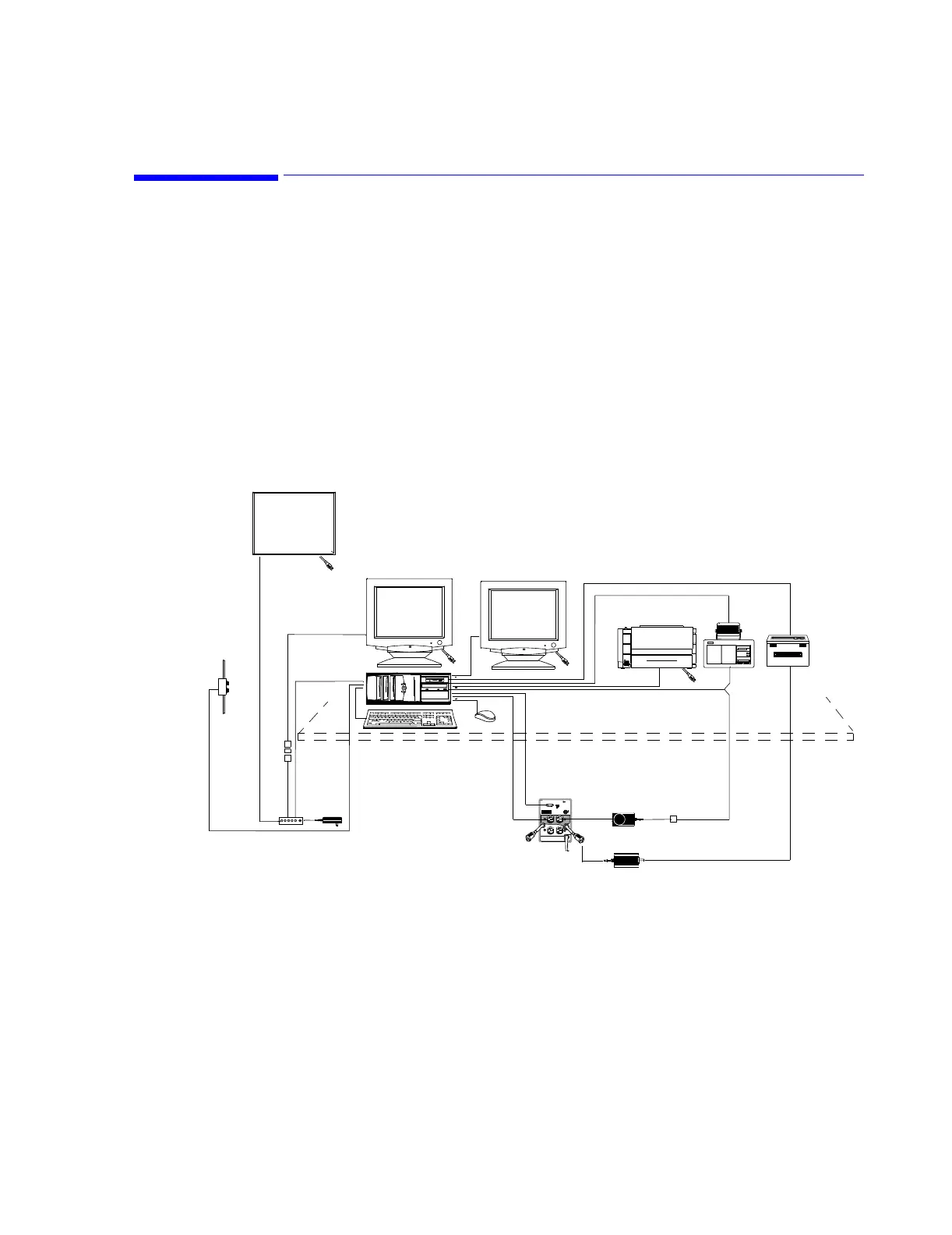
Once the Information Center system components have been positioned in their locations,
they can be interconnected using proper equipment cables. Wiring diagrams for the Database
Server and Information Center systems are given in this section. Diagrams for plug
connections to the processing unit and wiring diagrams for the total system, including
options, are provided. The key to cable numbers is given in Table 3. Follow the appropriate
figure to interconnect each unit of the system.
IntelliVue
Information
Center
The general layout of a typical Information Center installation is shown in Figure 5-19. Plug
connections for the PC Workstations are given in Figures 5-13 and 5-14.
Figure 5-19 Typical Layout of Information Center Installation
3 1/2
2
3
4
5
6
7
4
10
11
12
13
14
15
16
18
19
20
21
1
Optional Remote,
Slave Display
Main Screen Display
1
Optional Second Display
 Loading...