Configuring the System
Start-up and Configuration
8-17
Clinical
Network
Table 8-7 describes the test or inspection to perform for active M3185A Clinical Network
components for each type of test specified in Table 8-2.
Table 8-7. M3185 Clinical Network Components - Test and Inspection Matrix
Test Block
Name
Test or Inspection to Perform Expected Results
What to Record
on Service
Record
V
isual Inspect all system components for obvious damage. No visible damage V:P or V:F
where P = Pass
F = Fail
Power On: Power on each active Network device.
Observe that all lights visible on the front panel are in
proper status and that no error conditions are shown.
Following are normal conditions for each type of device:
J4813A HP2524 24 Port Switches:
After self test, the Power LED is solid green
Cisco 24 Port Switches:
After self test, the System Status LED is solid green
and all of the Port Status LEDs are Off (nothing is
connected to the front panel.)
J3300A Repeater Hubs:
After self test, the Power LED is solid green and the
Port and Fault LEDs are Off (nothing is connected to the
front panel).
If a J2606A Transceiver is installed, the Xcvr LED is
On. If it is not installed, it is Off.
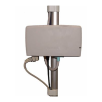
M3188A (M3185A-#C11) 100 Mbit/s UTP/Fiber Media
Translator:
With power on, the Power LED is solid green. The SDF,
SDC, RXC, and RXF LEDs can flash if data activity is
present.
J4097A HP408 Extension Switch:
After self test, the Power LED is solid green
M3189A (M3185A-#C21) Wireless Access Point:
After self test (~ 30 s), system Status LED (uppermost
LED on the top panel) is solid green. Other LEDs can be
on or off depending on whether data activity is present
Devices power up into
expected status; no error
indications are shown.
PO:P or PO:F
where P = Pass
F = Fail
 Loading...