Cables
2-44 Hardware Description
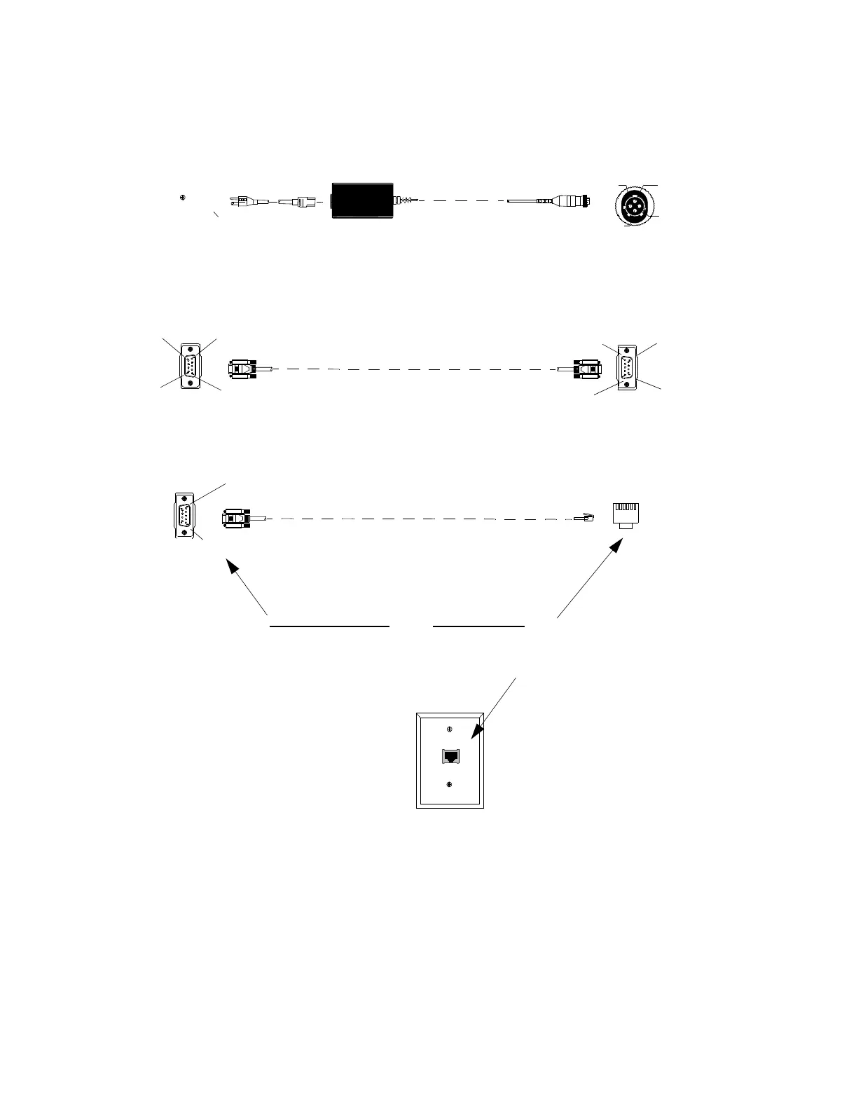
Figure 2-43 Pin Connections
SDN Wall Box and
Signal Cable
Pin connections for the SDN wall box and signal cable are given in Figure 2-44. UTP cable
from the SCC to the wall box consist of 4 pairs of unshielded, twisted wires. Pair 1 --
WHITE-blue and BLUE-white -- carries the SDN signal from the SCC and is connected to
AC Power
(UPS)
4-Channel Recorder
24 VDC Power Supply
Socket 1
Socket 3
Socket 4
Socket 2
Socket 1:Black Power Ground
Socket 2:
Socket 3: Outer Shield
Socket 4: Red: 24VDC
Pin 5
Pin 1
Pin 9
Pin 6
Pin 9
Pin 6
Pin 5
Pin 1
4-Channel Recorder
Serial - Serial Cable
(straight through)
SDN 9-pin D from SDN Card to standard
CAT 5 UTP faceplate (RJ45 connector)
Pin 1
Pins on D-9 Connector Pins on RJ45 Plug
3 -----------------------------------------> 5
8 -----------------------------------------> 4
5 -----------------------------------------> 1,2,3,6,7,8, Drain
Pin 5
 Loading...