Cables
Hardware Description
2-45
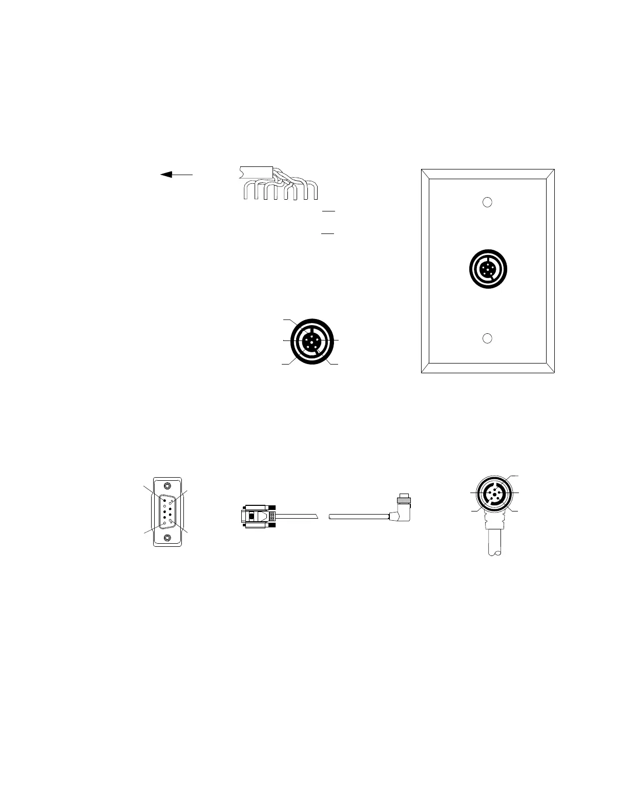
connections A (+) and E (-) of the SDN wall box socket. The other UTP cable pairs are
connected to ground.
Figure 2-44 Pin Connections for SDN Wall Box and Cable
UTP Cable
BODY
stripe
WHITE/blue
BLUE/white
WHITE/orange
ORANGE/white
WHITE/green
GREEN/white
WHITE/brown
BROWN/white
Pin Connections to the SDN Wall Box
to SCC
Pin Connections to the SDN Signal Cable
Processing
Unit
Pin 5
Pin 9
Pin 6
Pin 1
Pin 2 - Black: Priority Wire (-)
Pin 3 - Blue: Data Wire (-)
Pin 5 - Foil: Drain Wire Ground
Pin 7 - Gray: Priority Wire (+)
Pin 8 - Pink: Data Wire (+)
Wall Box
Pin A - Pink: Data Wire (+)
Pin B - Black: Priority Wire (-)
Pin C - Gray: Priority Wire (+)
Pin D - Foil: Drain Wire Ground
Pin E - Blue: Data Wire (-)
Pin E
Pin D
Pin C
Pin B
Pin A
Socket A
Socket E
Socket D
Socket C
Socket B
Socket A - BLUE/white: Data Wire (+)
Socket B - NC
Socket C - NC
Socket D - Drain Wire Ground
Socket E - WHITE/blue: Data Wire (-)
WHITE/blue: Data Wire (-)
BLUE/white: Data Wire (+)
All others: Ground
SDN Wall Box
 Loading...