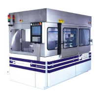
BD25A-AC Series
B-22
DESCRIPTION: The BD25A20AC Series PWM servo amplifiers are designed to drive brushless DC motors at a high
switching frequency. They are fully protected against over-voltage, over-current, over-heating and short-circuits. All models
interface with digital controllers that have a digital PWM output. PWM IN determines the output duty cycle. DIR IN
determines the direction of rotation. They require a single AC power supply. A single red/green LED indicates operating
status. The current limit can be set by DIP switches.
SPECIFICATIONS:
All BD25A20AC specifications are identical to the BD25A20 specifications (see BD30A Series) except for:
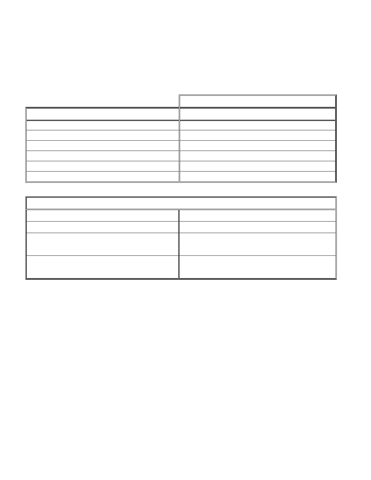
MODEL
POWER STAGE SPECIFICATIONS BD25A20AC
SHUNT RESISTOR
10 Ω @ 50 W
SHUNT SWITCH ON VOLTAGE 185 VDC
BUS CAPACITANCE
3600 µF
SHUNT FUSE (d = .25 inches, L = 1.25 inches) 3 A Motor Delay rated @ 250 VAC
BUS FUSE (5x20 mm) 16 A slow-blow rated @ 250 VAC
MECHANICAL SPECIFICATIONS
POWER CONNECTOR Screw terminals
SIGNAL CONNECTOR Molex connector
SIZE
7.35 x 4.23 x 2.45 inches
186.7 x 107.4 x 62.2 mm
WEIGHT
2.5 lb.
1.14 kg
These amplifiers contain a rectifier bridge and filter capacitors to generate the DC bus internally from the AC input power.
The DC bus voltage is 1.4 times AC voltage (RMS), e.g. 170 VDC from 120 VAC. During braking much of the stored
mechanical energy is fed back into the power supply and charges the output capacitor to a higher voltage. If the charge
reaches the amplifier's over-voltage shutdown point, output current and braking will cease. To ensure smooth braking of
large inertial loads, a built-in "shunt regulator" is provided in the BD25A20AC. The shunt regulator will switch-on the internal
power resistor when the bus voltage reaches 185 VDC. This resistor then dissipates the extra energy of the DC bus.
APPLICATION NOTE: Contact factory for information regarding the use of the current monitor pin (P1-15).
OPTICAL INPUT SIGNAL ISOLATION: PWM, DIR, INH, FAULT inputs are always isolated from the power section. On the
BD25A20AC series the Hall sensor inputs (P1-10 through 14) are also isolated.
ORDERING INFORMATION:
Models: BD25A20ACX
X indicates the current revision letter.
TYPICAL SYSTEM WIRING: See section “G”.
MOUNTING DIMENSIONS: See page F-11.


 To Next Page