34 Pamux User’s Guide
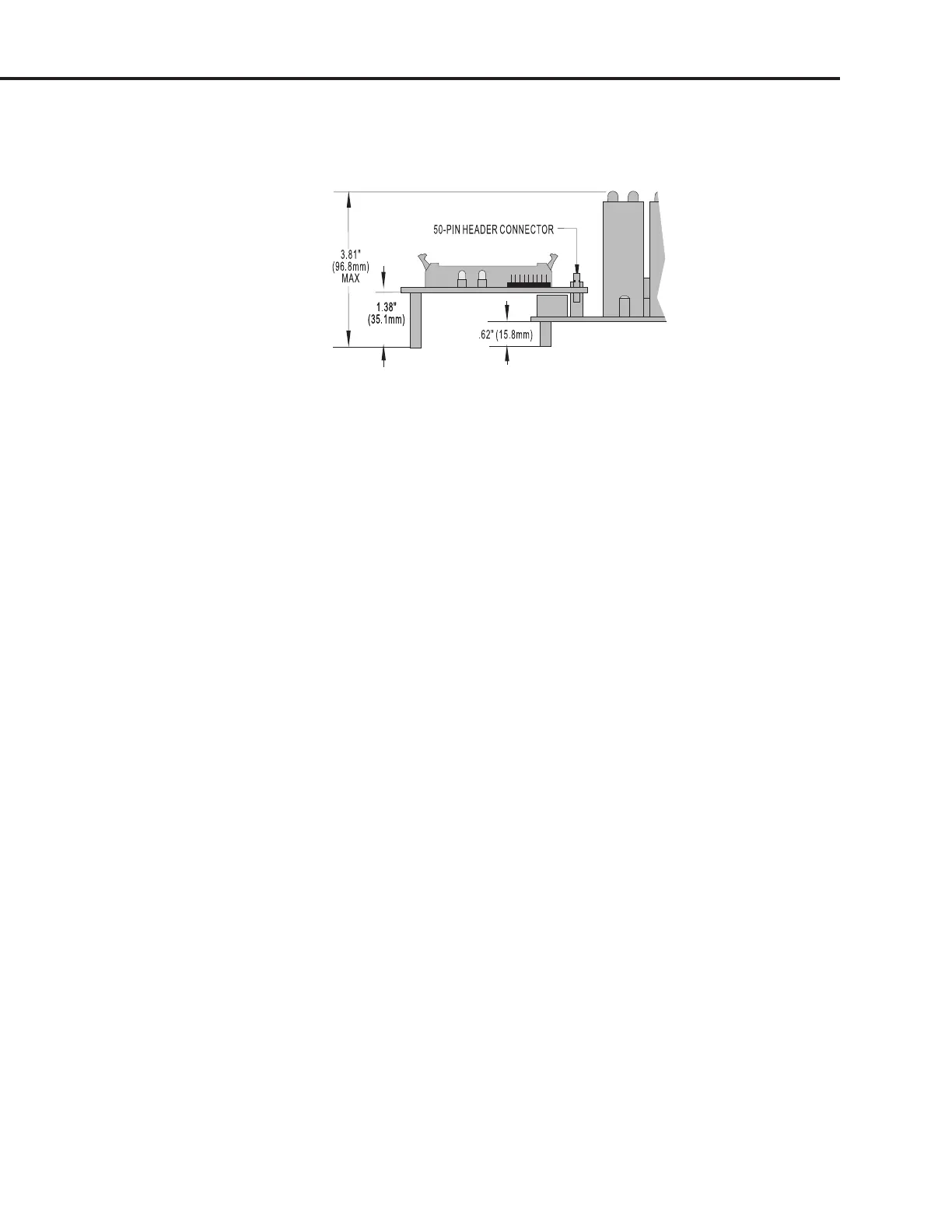
Figure 2-23 shows the vertical dimensions of the B5 mounted on the PB16HQ. This rack accepts quad
pak modules, which are taller than standard digital I/O modules.
Figure 2-23: Vertical Dimensions of the B5 Mounted on a PB16HQ
SETTING B5 JUMPERS
The B5 includes nine jumpers. Jumpers 0 through 4 set the address, jumpers 5 and 6 set the watchdog
functionality, jumper 7 sets the reset line polarity, and jumper 8 determines how the reset line affects
the watchdog timer.
Jumpers 0–4 (Address)
These jumpers configure the base address of the B5. Since the brain board controls 16 points of I/O,
while the Pamux data bus is only eight bits wide, the B5 must be accessed as two consecutive banks of
eight I/O channels each. The least significant bit of the Pamux address bus is used to select which bank
is accessed (0 = low bank, 1 = high bank). The other 5 bits of the Pamux bus address determine which
Pamux station is active.
Refer to Table 2-5 on the following page to determine how to set the base address of the B5.
Note: That each Pamux station on a bus must have a unique address.
Jumpers 5 and 6 (Watchdog)
A watchdog timer shuts down a process when the host computer goes off line. The watchdog timer on
the B5 depends on a periodic read or write strobe from the host processor. The individual B5 need not be
addressed. The absence of a strobe for a specified time activates the watchdog function.
Using jumpers 5 and 6, you can configure the B5 to trigger one of four actions upon a timeout. Refer to
Table 2-6 on page 2-19.
SYSTEM SETUP