36 Pamux User’s Guide
The watchdog timeout interval is set within the hardware and cannot be changed by the user. Refer to
Table 2-7 for minimum, typical, and maximum watchdog timeout values.
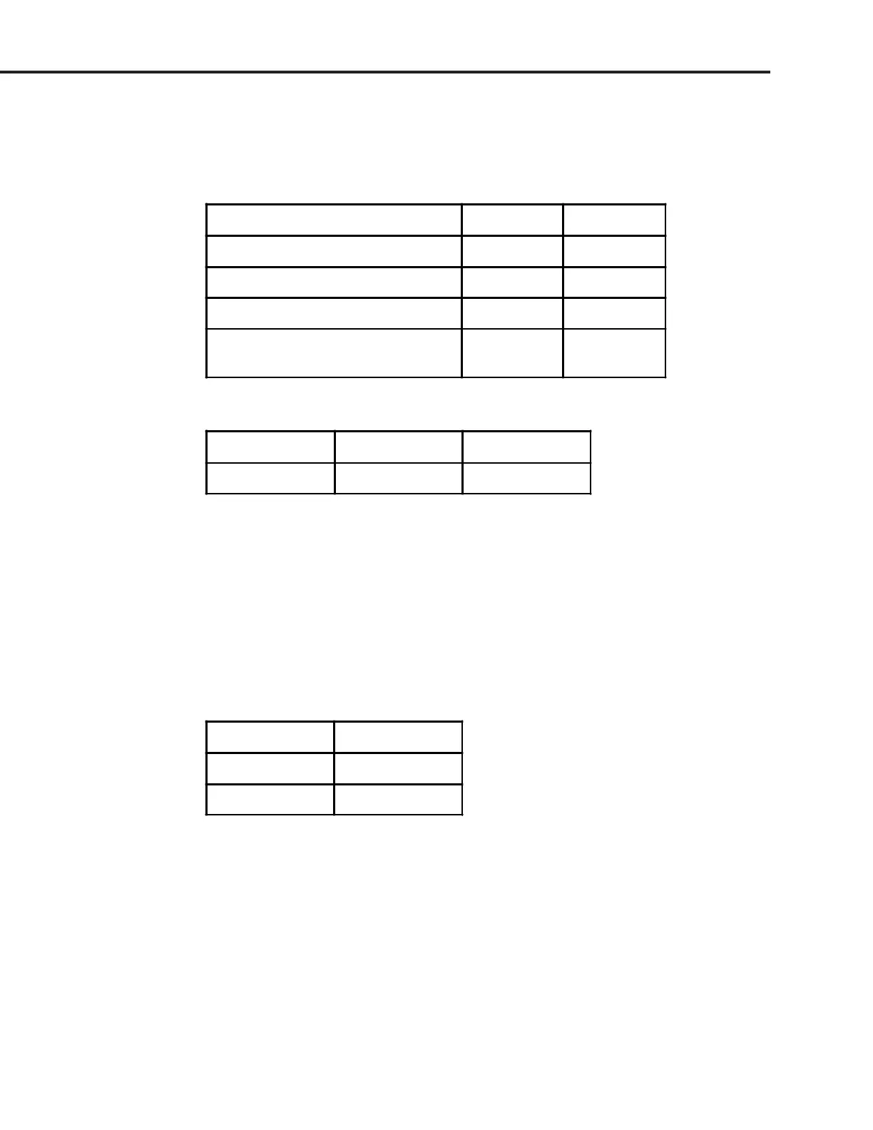
Table 2-6: B5 Watchdog Jumpers
Watchdog Function Jumper 6 Jumper 5
No action In In
Activate relay channel 0 In Out
Deactivate all relay channels Out In
Activate relay channel 0
and deactivate relay channels 1-15
Out Out
Table 2-7: Watchdog Timeout Values
Minimum Typical Maximum
1.0 sec 1.6 sec 2.25 sec
Jumpers 7 and 8 (Reset)
One of the control lines on the Pamux bus is the reset line. This line is used for turning off the relays on
all Pamux stations on the bus. Note that the reset is not intended to be used to shut off outputs upon a
system communication error.
Two jumpers control how the reset line affects the B5. Jumper 7 determines the polarity of the reset
line, either active high or active low, as shown in Table 2-8. In general, it does not matter which polarity
you select as long as you are consistent throughout your Pamux system.
Table 2-8: B5 Reset Jumper
Reset Level Jumper 7
Active High In
Active Low Out
Jumper 8 determines how the reset line affects the watchdog timer function of channel 0.
If jumper 8 is not installed, the reset line will not affect the watchdog timer function. Hence, if channel
0 activates due to a watchdog condition, an active reset line will have no effect on channel 0
(although it will deactivate any other channels that are on).
If jumper 8 is installed and the watchdog jumpers are configured to activate channel 0 upon a
timeout, the state of channel 0 depends on whether or not the reset activates before the timeout
occurs:
SYSTEM SETUP