Pamux User’s Guide 37
• If the reset line activates first, all outputs will deactivate. If a subsequent timeout occurs, no
effect will take place until the reset line deactivates, at which time the watchdog function
will take place and channel 0 will activate.
• If the timeout occurs first, the watchdog function takes place and channel 0 activates. If a
subsequent reset occurs, channel 0 will not be affected and will remain active.
TERMINATING A B5 STATION
For stations on a Pamux bus to operate correctly, both ends of the bus must be terminated. The
host computer and the last Pamux station on the bus are the only devices that should be terminated.
Note that if you are using an Opto 22 Pamux adapter card, the host computer is automatically
terminated, since termination resistors are built into the card.
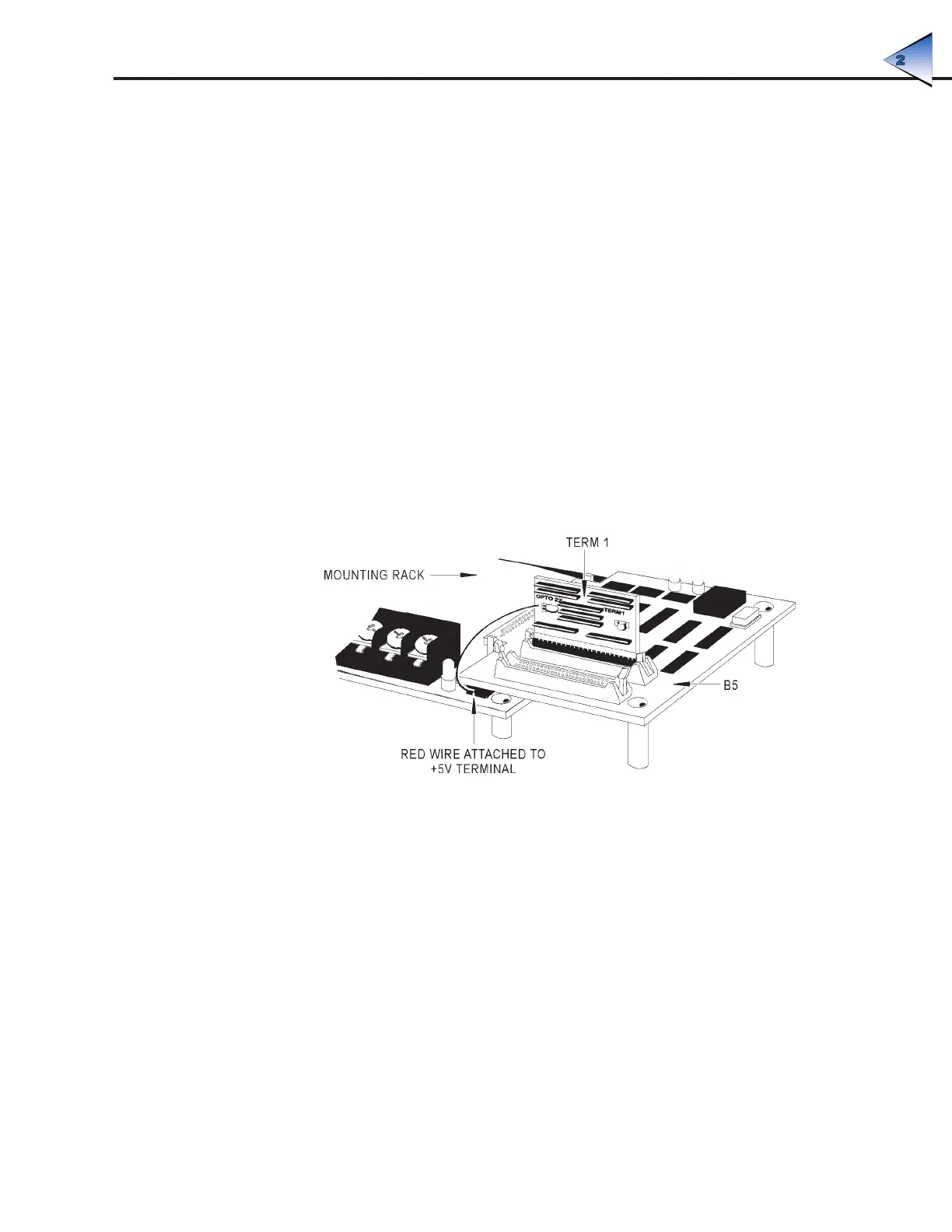
To terminate a B5 station, plug a Pamux bus terminator board (TERM1 or TERM2) into either
connector on the brain board. When the terminator board is installed correctly, its component side
faces away from the brain board components and its red wire connects to the +5V terminal on the
rack.
Figure 2-24 illustrates the proper installation of the terminator board.
Figure 2-24: Terminator Board Installed on a B5-Compatible Mounting Rack
B5 LED INDICATORS
The B5 brain board includes the following LEDs:
• Address — This LED is on whenever the brain board is addressed (read from or written to) on
the Pamux bus. It is off otherwise. For each operation the LED stays on for about 250 msec, so
if the bus is very active the LED may appear constantly on.
• Watchdog — This LED stays on if the Pamux bus is idle (no strobe is present) for more than
1.2 seconds. It is off otherwise. Note that unlike the Select LED, this LED monitors overall bus
activity.
SYSTEM SETUP