38 Pamux User’s Guide
SETTING UP A B6 STATION
This section describes how to install the B6 analog I/O brain board on a compatible mounting rack. It
also discusses B6 configuration issues, including how to set jumpers for the address, watchdog, and
reset line. Finally, it addresses how to install a terminator board when a B6 station is at one end of a
Pamux system and describes the LED indicators.
INSTALLING THE B6 ON A MOUNTING RACK
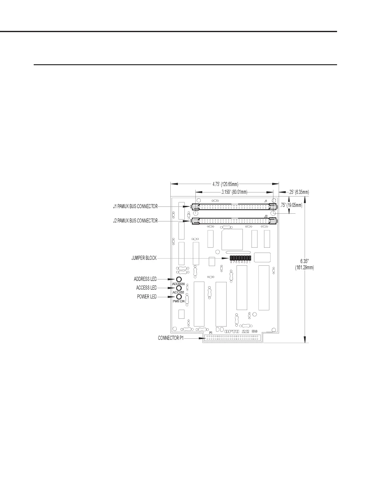
The B6 brain board measures 6.40 by 4.75 inches. It includes a 50-pin female connector to attach to an
analog I/O mounting rack. At the top of the brain board are two 50-pin male header connectors used to
link the brain board to the Pamux bus. For the last brain board on a Pamux bus, one of these connectors
holds the terminator board.
Figure 2-25 is a detailed illustration of the B6 along with its dimensions.
Figure 2-25: Dimensions of the B6 Brain Board
Three I/O mounting racks are available for the Pamux B6 brain board:
• PB4AH — 4-channels of single-point standard analog I/O
• PB8AH — 8-channels of single-point standard analog I/O
• PB16AH — 16-channels of single-point standard analog I/O
SYSTEM SETUP