40 Pamux User’s Guide
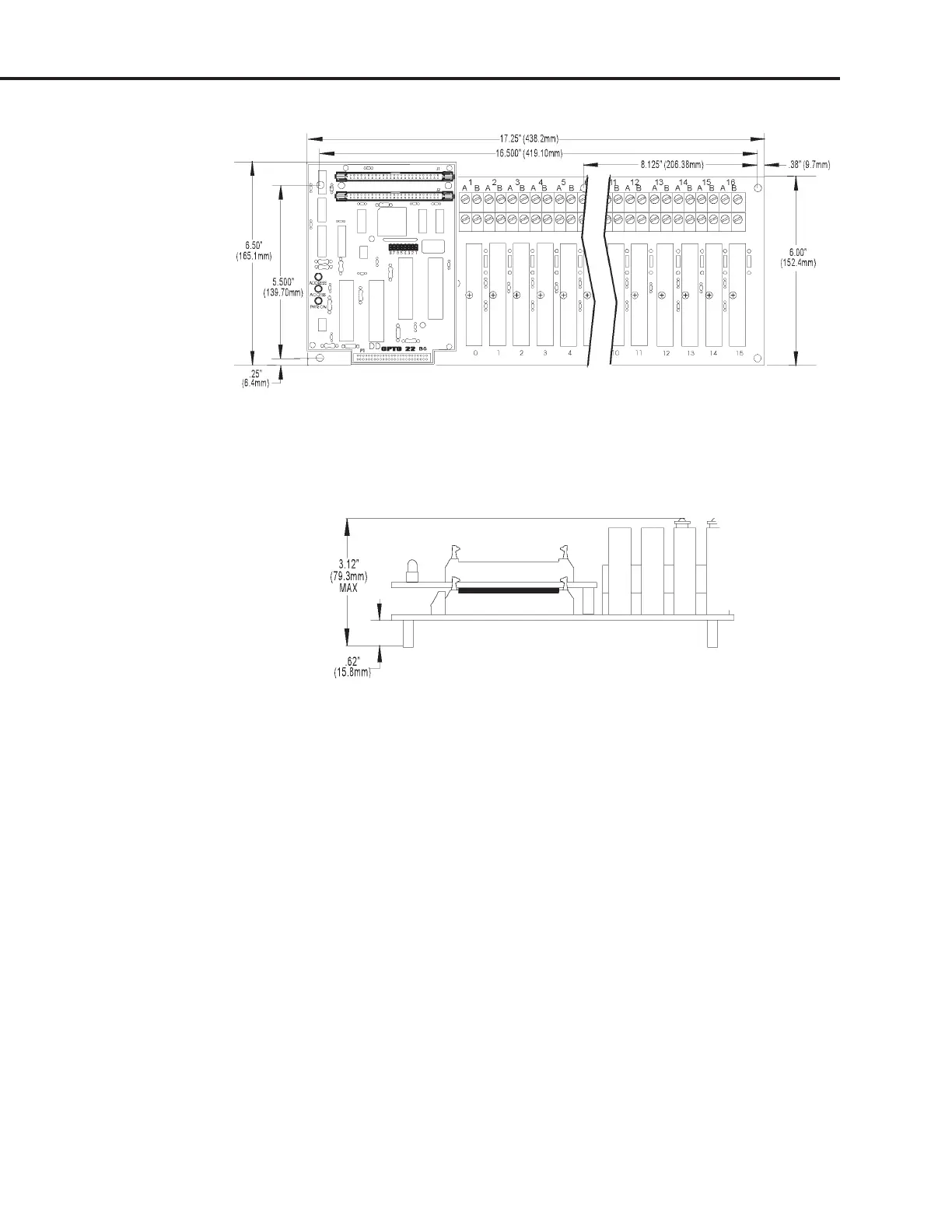
Figure 2-28: Mounting Dimensions of the PB16AH with a B6 Installed
Figure 2-29 shows the vertical dimensions of the B6 mounted on any rack.
Figure 2-29: Vertical Dimensions of the B6 Mounted on a Rack
SETTING B6 JUMPERS
The B6 includes eight jumpers. Jumpers 1 through 5 set the address, jumper 6 is disabled, jumper 7 sets
the reset line polarity, and jumper 8 sets the watchdog functionality.
Jumpers 1–5 (Address)
These jumpers configure the base address of the B6. The brain board can control 16 points of analog I/O.
Data is passed to and from the host computer using one address register and one data register. Each B6
thus requires only two consecutive addresses.
Refer to Table 2-9 on the following page to determine how to set the base address of the B6.
Note that each Pamux station on a bus must have a unique address.
SYSTEM SETUP