48 Pamux User’s Guide
Output Modules
Use Figure 2-31 on the previous page to wire the digital DC and AC output modules listed in Table
2-16. The diagram shows a DC output module wired to channel 6 and an AC output module wired to
channel 7 on a G4PB16H rack.
For the digital output modules listed in Table 2-16, the load may be wired to either line. The polarity of
the power does not matter except for the G4ODC5, G4ODC5A, G4ODC5MA, ODC5, ODC5A,
SNAPODC5SRC, and SNAPODC5SNK.
For DC output modules used with inductive loads, add a commutating diode (typically a 1N4005) to
the circuit as shown on the channel 6 connection to the G4PB16H rack.
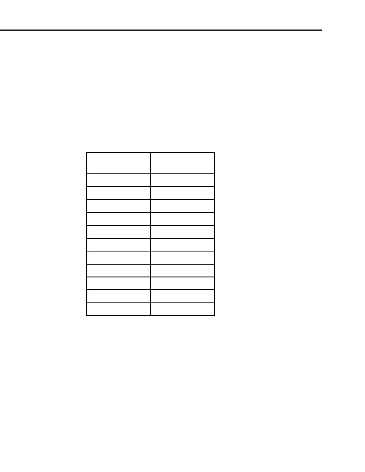
Table 2-16: Digital DC and AC Output Modules
DC Output
Modules
AC Output
Modules
G4ODC5 G4OAC5
G4ODC5A G4OAC5A
G4ODC5MA G4OAC5A5
G4ODC5R G4OAC5AMA
G4ODC5R5 G4OAC5MA
ODC5 G4ODC5R
ODC5A G4ODC5R5
ODC5R OAC5
SNAPODC5SRC, OAC5A
SNAPODC5SNK OAC5A5
- - - SNAPOAC5
SYSTEM SETUP