54 Pamux User’s Guide
0 to 5 Amp AC/DC Current Input Modules
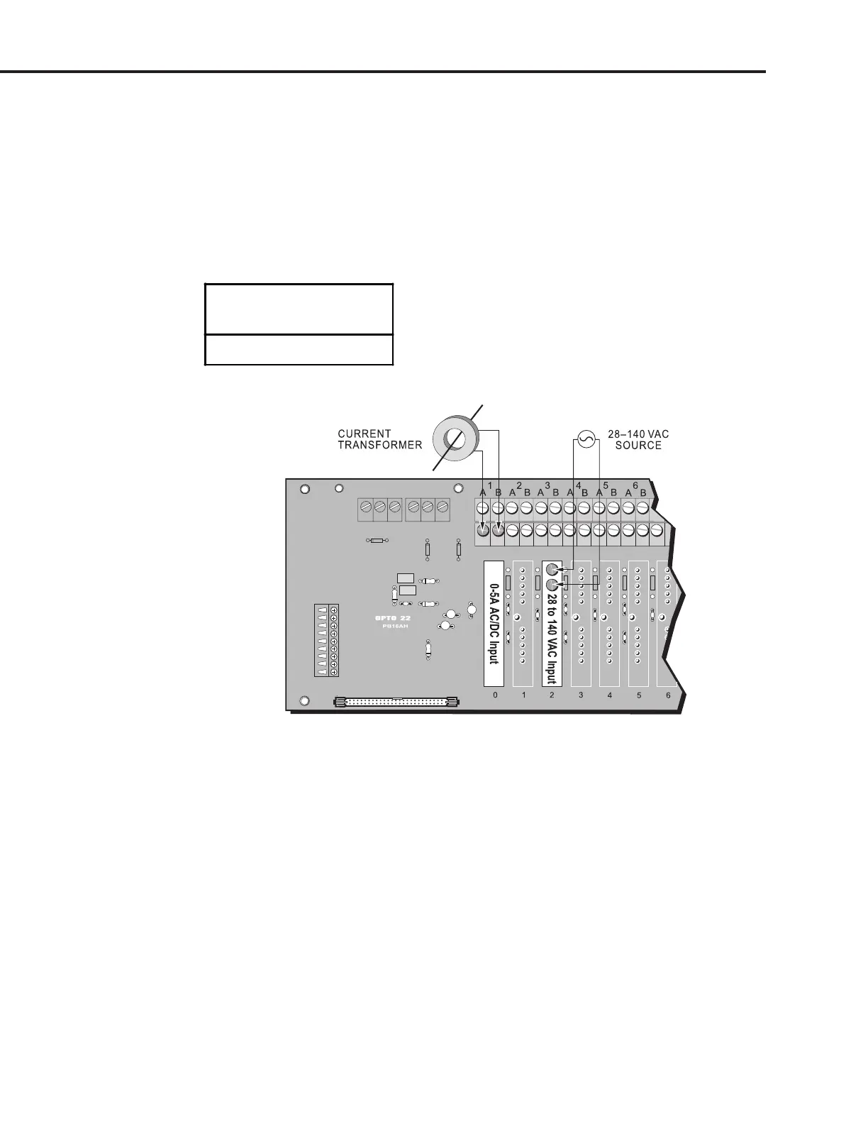
Use Figure 2-36 to wire the 0–5A AC/DC current input module listed in Table 2-21. The example shows
wiring of the AD16 to channel 0 on a PB16AH rack.
The 0–5A AC/DC current input module can be used to measure current directly or indirectly by using a
standard current transformer. Applications include measuring or monitoring current through a field
device such as a motor, solenoid, or lamp.
Table 2-21: 0 to 5 Amp AC/DC Current Input Module
0 to 5 Amp AC/DC
Current Input Module
AD16T
Figure 2-36: Wiring for 0–5A Current Input and 28–140 VAC Input Modules
Thermocouple Input Modules
Use Figure 2-37 to wire the analog thermocouple input modules listed in Table 2-22. The example
shows a thermocouple input module wired to channel 3 on a PB16AH rack.
When wiring thermocouples, verify that you are using the proper polarity and wire color (see Table
2-22). Also, ensure that the wire type from the thermocouple to field terminals is consistent and does
not introduce other thermocouples.
Thermocouple modules do not include a connection to the A and B terminals. Instead, the thermocouple
wires are attached to screws located directly on the module.
Some thermocouple modules require a linearization algorithm to convert readings to temperatures.
See Appendix C for details.
SYSTEM SETUP