Pamux User’s Guide 55
Table 2-22: Thermocouple Input Data
Modules T/C Type
Polarity/Color
+-
AD5, AD5T J White Red
AD8, AD8T K Yellow Red
AD17T R Black Red
AD18T T Blue Red
AD19T E Purple Red
AD17T S Black Red
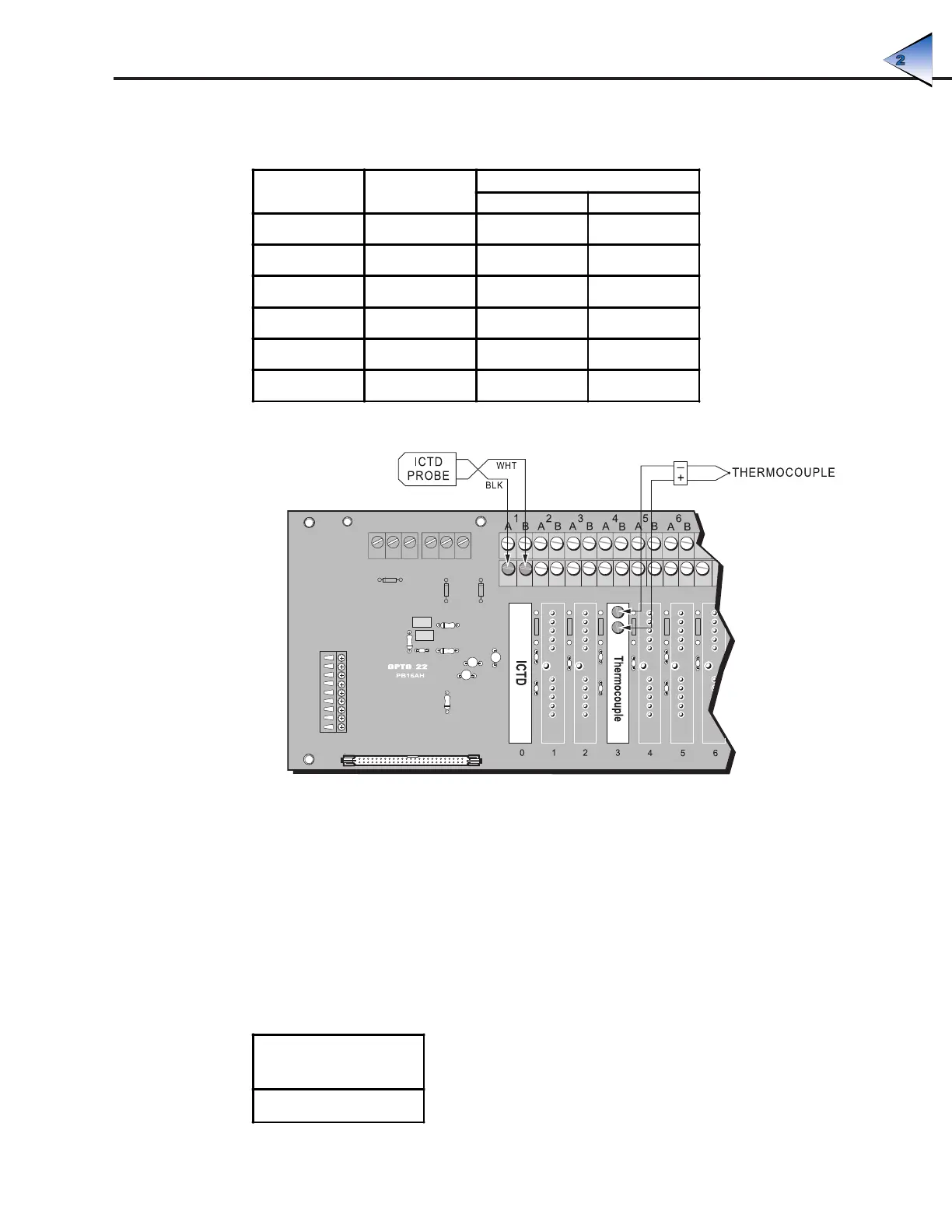
Figure 2-37: Wiring for Thermocouple and ICTD Temperature Input Modules
ICTD Temperature Input Modules
Use Figure 2-37 to wire the analog ICTD temperature input module listed in Table 2-23 to an Opto 22
ICTD probe. The example shows wiring to channel 0 on a PB16AH rack.
Note: That, like the thermocouple modules, ICTD modules also require a linearization algorithm to convert
readings to temperatures. See Appendix C for details.
Table 2-23: ICTD Temperature Input Module
ICTD Temperature
Input Module
AD4
SYSTEM SETUP