56 Pamux User’s Guide
RTD Input Modules
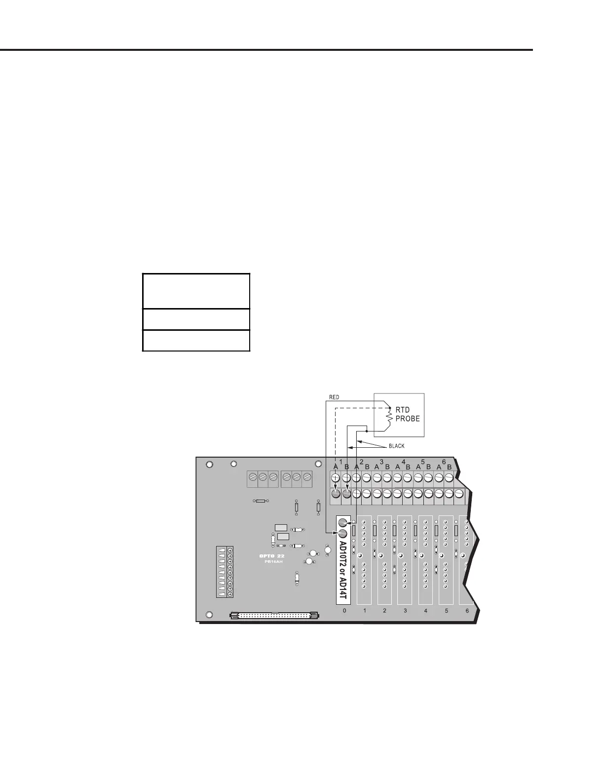
Use Figure 2-38 to wire the analog RTD input modules listed in Table 2-24. Wire colors may vary, but
make sure two wires of the same color are connected as shown. The example shows a three-wire
RTD probe connected to channel 0 on a PB16AH rack.
When using an AD10T2 with a four-wire RTD probe, do not connect the fourth wire. Connect three
wires as shown for the three-wire RTD example.
For a two-wire RTD probe, add a second wire of the same type and gauge to one end, connecting it
as you would a three-wire RTD.
Some RTD modules require a linearization algorithm to convert readings to temperatures. See
Appendix C for details.
Table 2-24: RTD Input Modules
RTD Input
Modules
AD10T2
AD14T
Figure 2-38: Wiring for RTD Input Modules
SYSTEM SETUP