Pamux User’s Guide 57
Rate Input Modules
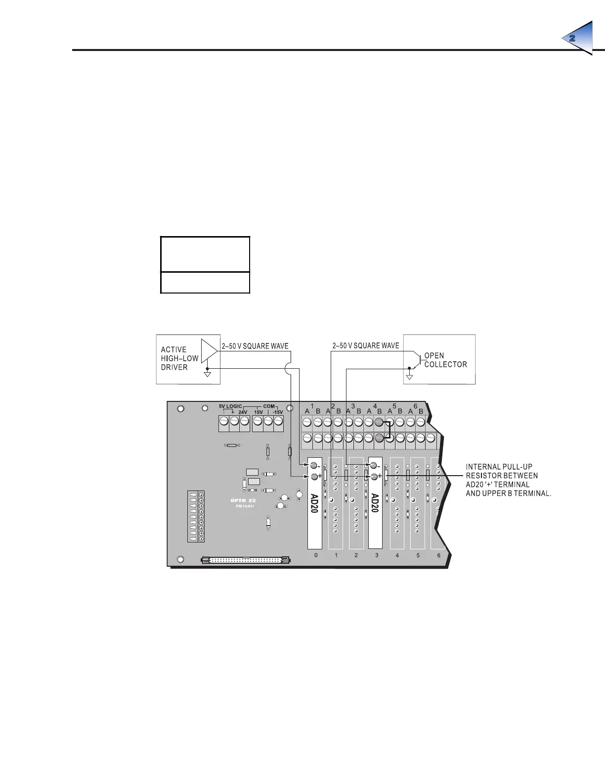
Use Figure 2-39 to wire the analog rate modules listed in Table 2-25. The example shows the possible
wiring options to channels 0 and 3 on a PB16AH rack. Note that the internal pull-up is between the
+ input post and the upper B terminal. Also, the – input and the upper A barrier terminal are connected
directly to the analog common when the module is plugged into the analog rack.
Rate modules measure the frequency of an incoming signal and produce a count based on the number
of cycles per second (Hertz). For example, a count value of 1,000 indicates a frequency of 1,000 Hz.
This module is ideal for directly reading the frequency of a signal or a rotating disk for RPM calculations,
for example.
Table 2-25: Rate Input Modules
Rate Input
Modules
AD20
Figure 2-39: Wiring for Rate Input Modules
SYSTEM SETUP