G4PB16I MOUNTING RACK
G4 Digital I/O Family Data Book 17
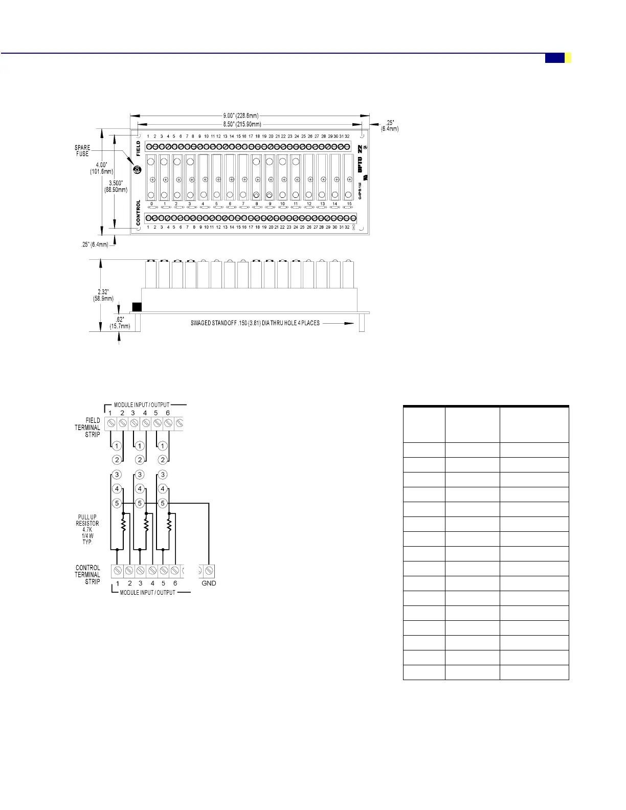
Dimensions—G4PB16I
Connections—G4PB16I
0RGXOH
3RVLWLRQ
&RQWURO
õ+HDGHU
&RQQHFWRUô
)LHOG
õ7HUPLQDO 6WULSô
í éæ ì DQG ë
ì éè ê DQG é
ë éê è DQG ç
ê éì æ DQG å
éêääDQGìí
èêæììDQGìë
ç êè ìê DQG ìé
æ êê ìè DQG ìç
å êì ìæ DQG ìå
ä ëä ìä DQG ëí
ìí ëæ ëì DQG ëë
ìì ëè ëê DQG ëé
ìë ëê ëè DQG ëç
ìê ëì ëæ DQG ëå
ìé ìä ëä DQG êí
ìè ìæ êì DQG êë
Notes:
1. At each module position on the field terminal
strip, the lower number is always connected to
pin 1 of the module.
2. Input modules and dry contact output modules
(G4ODC5R and G4ODC5R5) require the power
supply’s ground to be connected to the control
side’s GND terminal. These modules also
require that odd-numbered connections on the
control side be connected to +VCC.
3. Input modules use even-numbered control
terminals and can only be wired for
negative-true logic.
4. To wire output modules for standard
negative-true logic, connect the odd-numbered
control terminals to VCC and use the
even-numbered terminals for control.
5. To wire output modules for positive-true logic,
connect the even-numbered control terminals
to logic ground and use the odd-numbered
terminals for control.
See application examples on the following page.