Atmospheric Single-Arm Robot Manual
4000-0016 Rev A
80
Controller Internal Connection and Port G
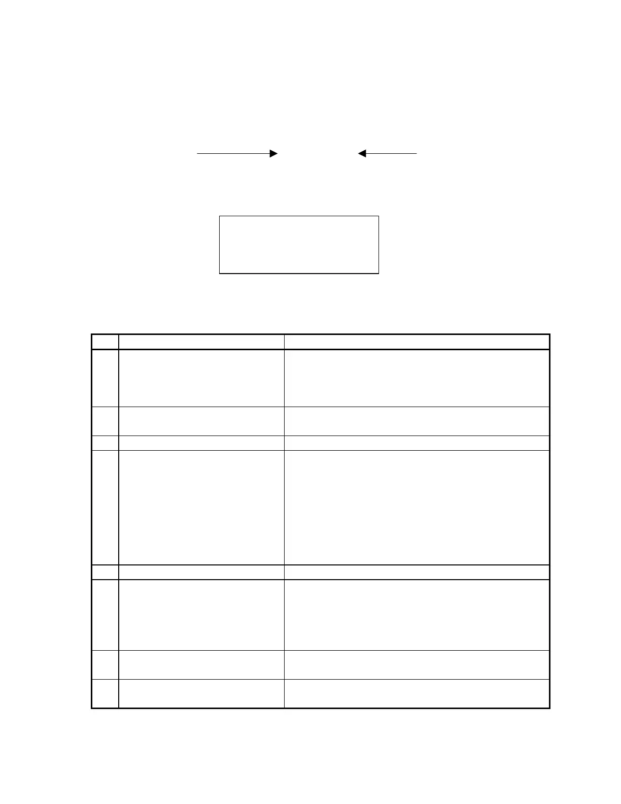
In the display, the order of XXXXXXXX, Bit 0 to Bit 7, is left to right.
Bit 0 XXXXXXXX Bit 7
That is, the left-most digit is the least significant bit (LSB) and the right-
most digit is the most significant bit (MSB).
When all cables, including the Robot signal cable, are connected, Input
port G should be all zeros. The following table describes each bit when it
is set to 1 and how to correct the problem.
Bit Description Corrective Action
0 Internal amplifier connections
or robot signal cable.
Check I/O to Galil cable, I/O to amplifier board,
and the signal cable. If all cables are OK, replace
the I/O board. If a problem persists, replace the
robot interface board.
1 Motor off. Check the interlock switch (EMS/MOFF) to ensure
it is in the correct state.
2 Stop input. Check stop input.
3 Amplifier Board Under Power
indicator
Check green LED on amplifier board.
• If ON (board under power), check I/O to
amplifier board cable and I/O board.
•
If OFF (board has no power), and there is
voltage to the amplifier board (P3 pin # 2 and 3
should be 41V to 46V), replace the amplifier
board. If no voltage, check motor power supply
(torroidal transformer) and relay.
4 Motor Power Supply indicator Check I/O to power supply cable and I/O board.
5 Robot Interface Board Power
Supply indicator. Usually
accompanied by bit 3.
Check the Power Supply board (located above the
switching power supply).
If the LED lights, check I/O to power supply cable
and I/O board.
If LED is not ON, check relay input for 5V.
6 Switcher indicator None. This condition occurs approximately 30 ms
before the controller shuts down.
7 Bus Power Good indicator None. The diagnostics software never observes this
condition.
Testing Input G
VALUE:
XXXXXXXX
Generate Error