Zynq-7000 AP SoC and 7 Series FPGAs MIS v4.1 369
UG586 November 30, 2016
www.xilinx.com
Chapter 2: QDR II+ Memory Interface Solution
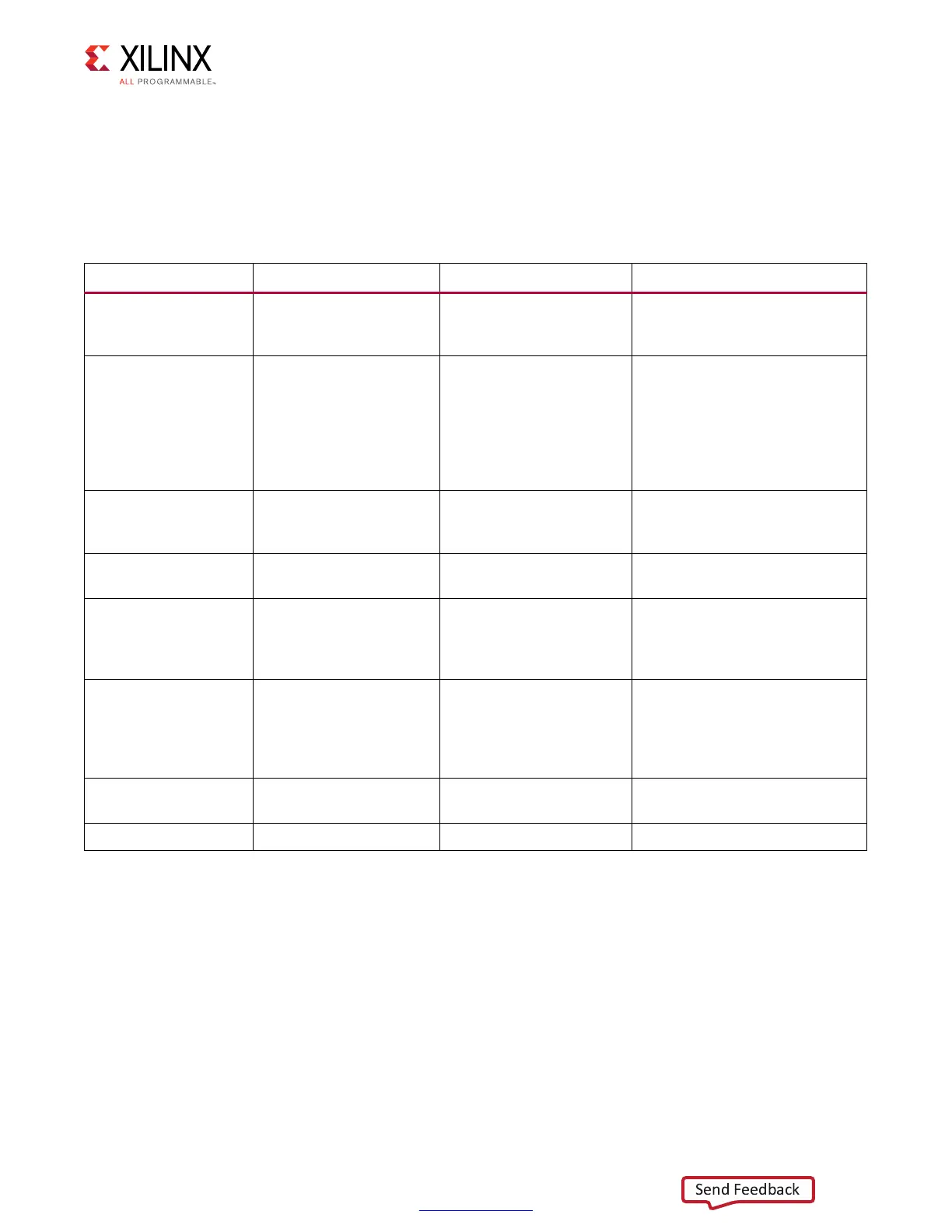
When running the core in hardware, a few key signals should be inspected to determine the
status of the design. The dbg_phy_status bus described in Table 2-16 consists of status
bits for various stages of calibration. Checking the dbg_phy_status bus gives initial
information that can aid in debugging an issue that might arise, determining which portion
of the design to look at, or looking for some common issues.
The read calibration results are provided as part of the Debug port as various output
signals. These signals can be used to capture and evaluate the read calibration results.
Read calibration uses the IODELAY to align the capture clock in the data valid window for
captured data. The algorithm shifts the IODELAY values and looks for edges of the data valid
window on a per-byte basis as part of the calibration procedure.
Table 2-16: Physical Layer Simple Status Bus Description
Debug Port Signal Name Description If Issues Arise
dbg_phy_status[0] rst_wr_clk
FPGA logic reset based on
PLL lock and system input
reset
If this signal stays asserted,
check your clock source and
system reset input
dbg_phy_status[1]
io_fifo_rden_cal_done &
po_ck_addr_cmd_delay_
done
I/O FIFO initialization to
ensure the I/O FIFOs are
in an almost full condition
and the phaser out delay
to provide the 90° phase
shift to address/control
signals are done
Check if the PHY control ready
signal is asserted
dbg_phy_status[2] init_done
QDR II+
SRAM
initialization sequence is
complete
N/A
(1)
dbg_phy_status[3] cal_stage1_start
Stage 1 read calibration
start signal
N/A
dbg_phy_status[4] edge_adv_cal_done
Stage 1 calibration is
complete and edge_adv
calibration is complete
Stage 1 calibration did not
happen right. Make sure valid
read data is seen during stage1
calibration.
dbg_phy_status[5] cal_stage2_start
Latency calibration start
signal after pi_edge_adv
calibration is completed.
If this signal does not go High,
then stage 1 has not completed.
Make sure the expected data is
being returned from the
memory.
dbg_phy_status[6]
cal_stage2_start &
cal_done
Latency calibration start
signal
N/A
dbg_phy_status[7] Cal_done Calibration complete N/A
Notes:
1. N/A indicates that as long as previous stages have completed, this stage is also completed.
 Loading...


