Zynq-7000 AP SoC and 7 Series FPGAs MIS v4.1 626
UG586 November 30, 2016
www.xilinx.com
Chapter 4: LPDDR2 SDRAM Memory Interface Solution
SYSCLK_TYPE
This parameter indicates whether the
system uses single-ended system clocks,
differential system clocks, or is driven from
an internal clock (No Buffer). Based on the
selected CLK_TYPE, the clocks must be
placed on the correct input ports. For
differential clocks, sys_clk_p/sys_clk_n must
be used. For single-ended clocks, sys_clk_i
must be used. For the No Buffer option,
sys_clk_i, which appears in port list, needs to
be driven from an internal clock.
DIFFERENTIAL
SINGLE_ENDED
NO_BUFFER
REFCLK_TYPE
This parameter indicates whether the
system uses single-ended reference clocks,
differential reference clocks, is driven from
an internal clock (No Buffer), or can connect
system clock inputs only (Use System Clock).
Based on the selected CLK_TYPE, the clocks
must be placed on the correct input ports.
For differential clocks, clk_ref_p/clk_ref_n
must be used. For single-ended clocks,
clk_ref_i must be used. For the No Buffer
option, clk_ref_i, which appears in the port
list, needs to be driven from an internal
clock. For the Use System Clock option,
clk_ref_i is connected to the system clock in
the user design top module.
DIFFERENTIAL
SINGLE_ENDED
NO_BUFFER
USE_SYSTEM_CLOCK
CLKIN_PERIOD Input clock period.
CLKFBOUT_MULT
PLL voltage-controlled oscillator (VCO)
multiplier. This value is set by the MIG tool
based on the frequency of operation.
CLKOUT0_DIVIDE,
CLKOUT1_DIVIDE,
CLKOUT2_DIVIDE,
CLKOUT3_DIVIDE
VCO output divisor for PLL outputs. This
value is set by the MIG tool based on the
frequency of operation.
DIVCLK_DIVIDE
PLLE2 VCO divisor. This value is set by the
MIG tool based on the frequency of
operation.
USE_DM_PORT
This is the enable data mask option used
during memory write operations.
0 = Disable
1 = Enable
CK_WIDTH
This is the number of CK/CK# outputs to
memory.
DQ_CNT_WIDTH This is ceil(log2(DQ_WIDTH)).
DRAM_TYPE
This is the supported memory standard for
the Memory Controller.
LPDDR2
DRAM_WIDTH
This is the DQ bus width per DRAM
component.
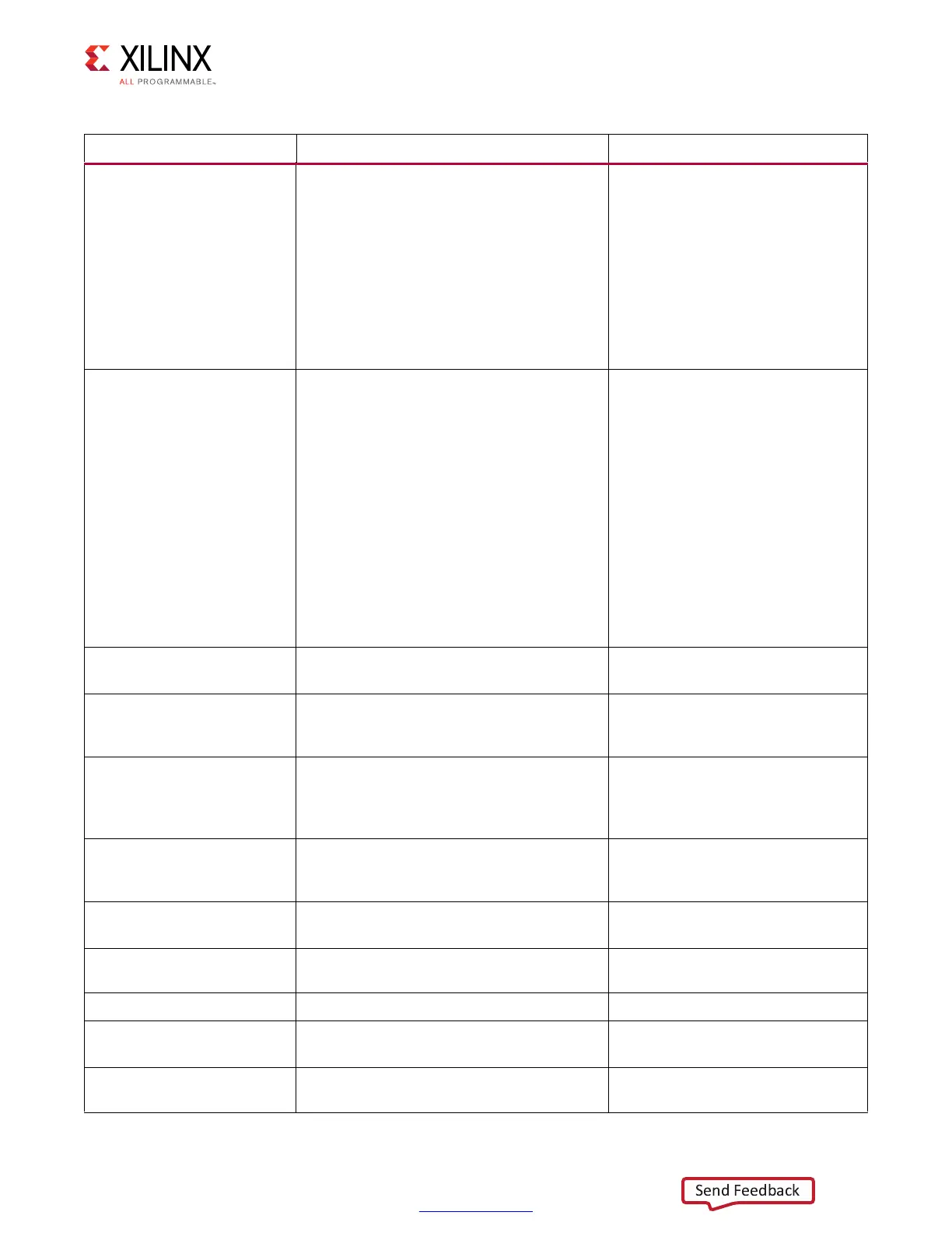
Table 4-26: Embedded 7 Series FPGAs Memory Solution Configuration Parameters (Cont’d)
Parameter Description Options
 Loading...


