Zynq-7000 AP SoC and 7 Series FPGAs MIS v4.1 627
UG586 November 30, 2016
www.xilinx.com
Chapter 4: LPDDR2 SDRAM Memory Interface Solution
Table 4-27 contains parameters set up by the MIG tool based on the pinout selected. When
making pinout changes, Xilinx recommends rerunning the MIG tool to set up the
parameters properly. See Bank and Pin Selection Guides for LPDDR2 Designs, page 631.
Mistakes to the pinout parameters can result in non-functional simulation, an unroutable
design, and/or trouble meeting timing. These parameters are used to set up the PHY and
route all the necessary signals to and from it. The following parameters are calculated based
on selected Data and Address/Control byte groups. These parameters do not consider the
system signals selection (that is, system clock, reference clock and status signals).
nBANK_MACHS
This is the number of bank machines. A
given bank machine manages a single
DRAM bank at any given time.
2, 3, 4, 5, 6, 7, 8
DATA_BUF_ADDR_WIDTH
This is the bus width of the request tag
passed to the Memory Controller. This
parameter is set to 4. This parameter should
not be changed.
4
RANKS This is the number of ranks.
DATA_WIDTH
This parameter determines the write data
mask width and depends on whether or not
ECC is enabled.
DATA_WIDTH = DQ_WIDTH
APP_DATA_WIDTH
This UI_INTFC parameter specifies the
payload data width in the UI.
APP_DATA_WIDTH =
2 × nCK_PER_CLK ×
PAYLOAD_WIDTH
APP_MASK_WIDTH
This UI_INTFC parameter specifies the
payload mask width in the UI.
USER_REFRESH
This parameter indicates if you manage
refresh commands. Can be set for either the
User or Native interface.
“ON,” “OFF”
Table 4-26: Embedded 7 Series FPGAs Memory Solution Configuration Parameters (Cont’d)
Parameter Description Options
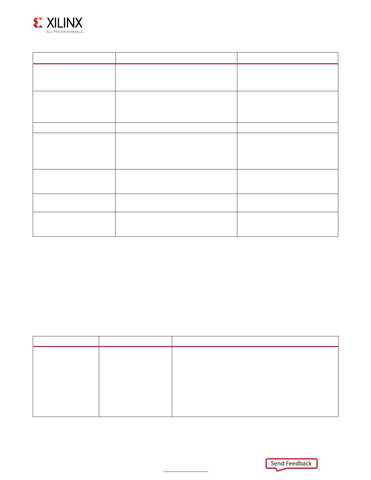
Table 4-27: LPDDR2 SDRAM Memory Interface Solution Pinout Parameters
Parameter Description Example
BYTE_LANES_B0,
BYTE_LANES_B1,
BYTE_LANES_B2
Defines the byte lanes
being used in a given I/O
bank. A 1 in a bit position
indicates a byte lane is
used, and a 0 indicates
unused. This parameter
varies based on the pinout
and should not be
changed manually in
generated design.
Ordering of bits from MSB to LSB is T0, T1, T2, and T3 byte
groups.
4'b1101: For a given bank, three byte lanes are used and one
byte lane is not used.
 Loading...


