Reference Manual ADuCM356
PROGRAMMABLE SWITCHES CONNECTING THE EXTERNAL SENSOR TO THE HIGH-SPEED DAC
AND HIGH-SPEED TIA
analog.com Rev. A | 114 of 312
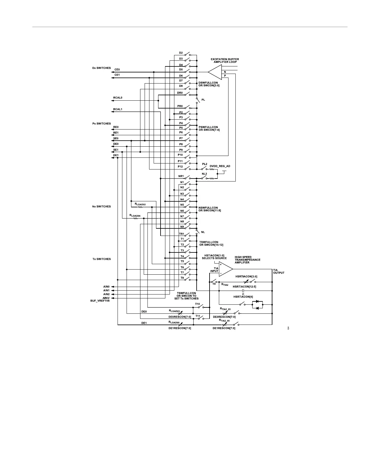
Figure 27. Switch Matrix Block Diagram, All Switches Connected to High-Speed DAC Excitation Amplifier and Inverting Input of High-Speed TIA
There are two options to control the programmable switches to
the high-speed DAC excitation amplifier and the high-speed TIA
inverting input: SWCON, Bit 16 = 0 and SWCON, Bit 16 =1.
For SWCON, Bit 16 = 0, the bit selects the SWCON register as
the control source for these switches. The transmit, Nx, Px, and Dx
switches are controlled in groups as follows:
► Transmit switches are controlled via SWCON, Bits[15:12]. A
single external pin is selected as the T input to the inverting input
of the high-speed TIA.
► Nx switches are controlled via SWCON, Bits[11:8]. A single
external pin is selected as the N input to the excitation amplifier
of the high-speed DAC.
► Px switches are controlled via SWCON, Bits[7:4]. A single exter-
nal pin is selected as the P input to the excitation amplifier of the
high-speed DAC.
► Dx switches are controlled via SWCON, Bits[3:0]. A single exter-
nal pin is selected as the D output of the excitation amplifier of
the high-speed DAC.
For SWCON, Bit 16 = 1, each switch can be individually configured
as follows:
 Loading...