A
B
C
D
E
F
G
H
L
M
N
P
Uso e manutenzione
Use and Maintenance operations
sezione / section
D 5
62 749/749 DARK/749S Aggiornamento/Update - M.Y. 2006 - edizione/edition 00
Controllo compressione
cilindri motore
Note
I simboli delle icone utilizzate
nella procedura sono riportati in una
tabella alla fine della presente sezione.
Il rendimento del motore è
direttamente correlato con il valore
di pressione che si può misurare
nelle camere di combustione dei
due gruppi termici.
Una pressione eccessiva od
insufficiente, così come una
eccessiva differenza tra i due
cilindri, produce sicuramente un
calo prestazionale del motore e
può essere causa di rotture.
Riscaldare il motore lasciandolo in
funzione fino all’inserimento, almeno
una volta, dell’elettroventola.
Rimuovere il gruppo codone
serbatoio (Sez. E 3).
Aprire completamente le farfalle.
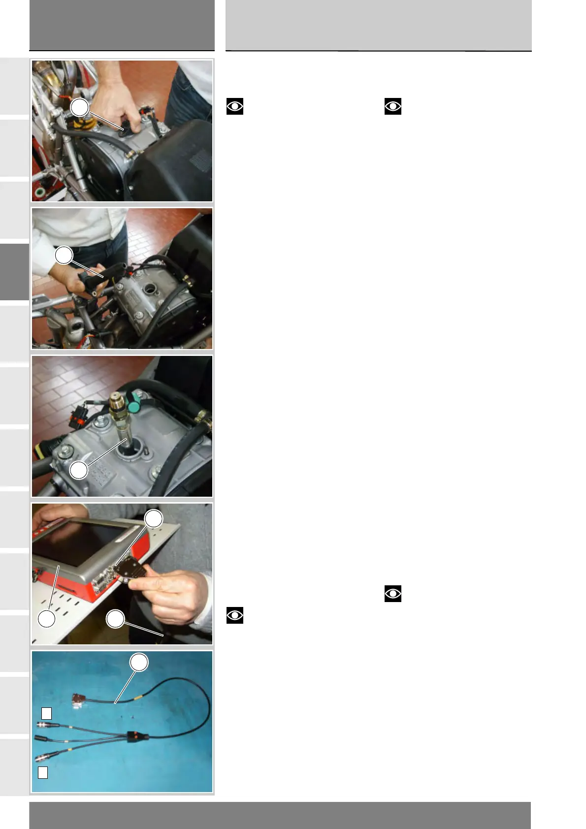
Rimuovere i cavi candele-bobina (21)
svitando i dadi (20) di entrambe le
candele.
Rimuovere la candela del cilindro da
controllare.
Mettere a massa il cavo della candela
per evitare la produzione di scintille.
Avvitare nella sede della candela il
cavo compressione cilindri (11).
Collegare il sensore pressione (5) al
cavo (11).
Accendere lo strumento DDS (1)
facendo riferimento al paragrafo
“Connessione alla moto”.
Collegare il cavo alimentazione e
diagnosi (Modulo Misure) (3) al
connettore modulo misure (B)
dello strumento DDS (1).
Collegare il sensore pressione (5) alla
presa (A) o (C) del cavo (3).
Note
Rilevare il valore operando su
un solo cilindro per volta.
Cylinder compression
test
Notes
The on-screen icons used
during this procedure are explained in
a table at the end of this section.
The efficiency of the engine is directly
correlated to the pressure that can
be measured in the combustion
chambers of the two cylinders.
Excessive or insufficient pressure,
or an excessive difference between
the two cylinders, will result in a
reduction in engine performance
and can lead to failure of parts.
Run the engine and allow it to
warm up to the point at which fan
operation starts, at least once.
Remove the tank-tail guard assembly
(Sect. E 3).
Open the throttles completely.
Remove the coil-spark plug cables (21),
unscrewing the nuts(20) of both spark
plugs.
Remove the spark plug from the
cylinder to be tested.
Connect the spark plug cable to
ground to prevent sparking.
Screw the cylinder compression
fitting (11) into the spark plug bore.
Connect the pressure sensor (5) to
the cable (11).
Switch on the DDS tester (1); see
heading “Connection to the
motorcycle”
Connect the power and diagnostics
cable (Measurement Module) (3)
to the measurement module
connector (B) on the DDS tester (1).
Connect the pressure sensor (5) to
socket (A) or (C) of the cable (3).
Notes
Measure the compression
working on one cylinder at a time.
20
21
11
B
1 3
A
C
3