A
B
C
D
E
F
G
H
L
M
N
P
Motore
Engine
sezione / section
N 6.2
119 749/749 DARK/749S Aggiornamento/Update - M.Y. 2006 - edizione/edition 00
Smontaggio coperchio
frizione
Note
Per una migliore chiarezza
le immagini rappresentano un
motore rimosso dal telaio.
Svitare e rimuovere le sei viti corte (5),
le vite lunghe (15) e (19) di fissaggio
del coperchio frizione (14).
Aiutandosi con un martello di
plastica, battere in vari punti sul
contorno del coperchio per favorire il
distacco dello stesso dal semicarter.
Rimuovere il coperchio frizione dal
semicarter facendo attenzione alla
boccola di centraggio (1).
Importante
È possibile rimuovere il coperchio
frizione (14) completo di campana
frizione e ingranaggio primario.
Sfilare dal semicarter la guarnizione
OR (2) in prossimità del foro di
passaggio olio.
Scomposizione
coperchio frizione
Rimuovere dal coperchio il tappo (3) e
relativa guarnizione OR (7), il sensore
pressione olio motore (9) e relativa
guarnizione (8), il tappo (16) e la
relativa guarnizione (17).
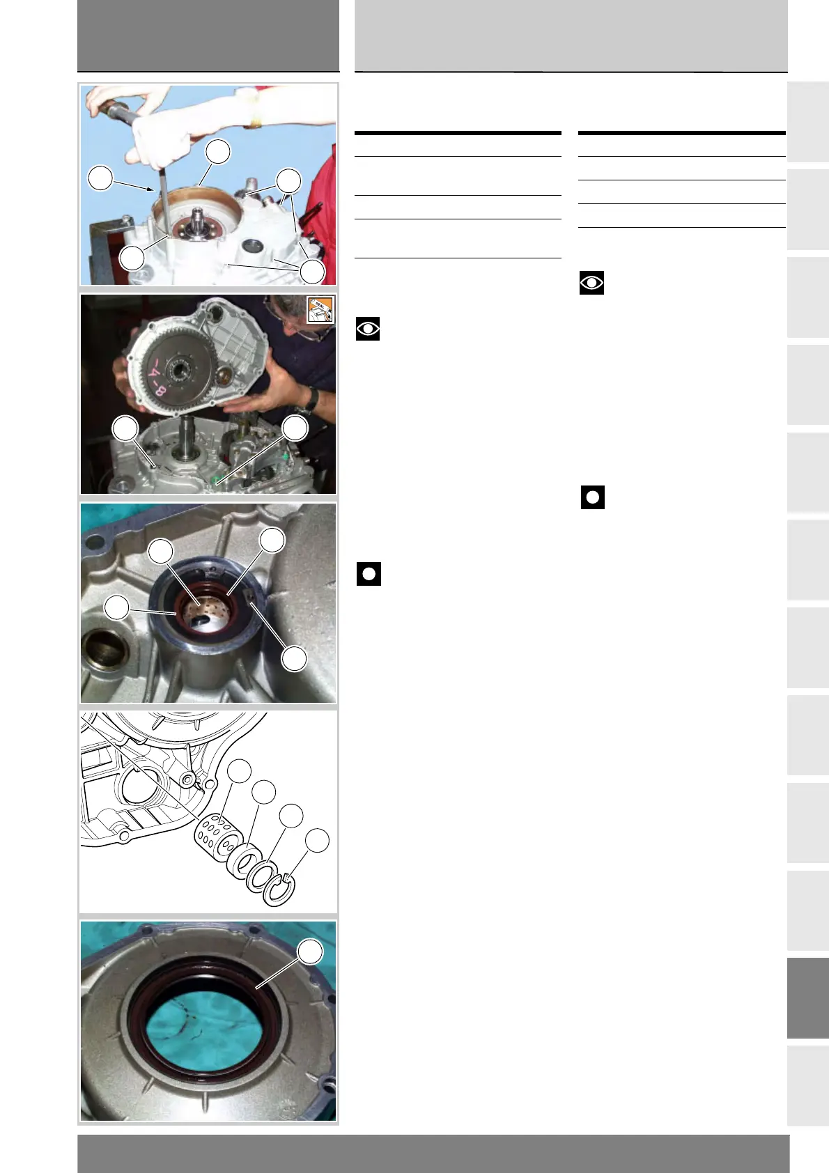
Rimuovere l'anello seeger (13) e
sfilare il rasamento (12) e l'anello di
tenuta (11).
La boccola forata (10) è montata a
interferenza sul coperchio. Per la
sua rimozione è necessario disporre
di un estrattore adatto.
Verificare visivamente le condizioni
dell'anello di tenuta (11) ed
eventualmente sostituirlo.
Per verificare le condizioni
dell'anello di tenuta (6) montato nel
coperchio frizione, tra campana
frizione e ingranaggio primario, è
necessario rimuovere detti
componenti (Sez. N 6.1).
Operazioni Rif. Sez.
Rimuovere le carene
laterali
E 2
Scaricare l’olio motore D 4
Rimuovere il sensore
olio
P 5
Rimuovere il tamburo
frizione
N 6.1
Removing the clutch
cover
Notes
For clarity, the figures show the
engine removed from the frame.
Unscrew and remove the six short
srews (5) and the long screws (15)
and (19) securing the clucth cover (14).
Tap around the edge of the covert
with a plastic mallet to detach it
from the crankcase.
Remove the clutch cover from the
crankcase. Do not the damage
locating bush (1).
Important
The clutch cover (14) can
be removed complete with clutch
housing and primary drive gear.
Remove the O-ring (2) located next to
lubrication hole from the crankcase.
Disassembly of the
clutch cover
Remove the plug (3) and O-ring (7),
engine oil pressure sensor (9) and
gasket (8), plug (16) and gasket (17)
from the cover.
Remove the circlip (13) and withdraw
the shim (12) and the oil seal (11).
The drilled bush (10) is mounted to
the cover by a forced interference fit.
Remove it with a suitable puller.
Visually check the seal (11) and
renew it if necessary.
To check the condition of the oil
seal (6) installed in the clutch cover
between the housing and primary
drive gear, remove first the latter
two components (Sect. N 6.1).
Operation See Sect.
Remove the side fairings E 2
Drain the engine oil D 4
Remove the oil sensor P 5
Remove the clutch drum N 6.1
14
19
5
5
15
1
2
11
10
12
13
10
11
12
13
6