A
B
C
D
E
F
G
H
L
M
N
P
Uso e manutenzione
Use and Maintenance operations
sezione / section
D 5
45 749/749 DARK/749S Aggiornamento/Update - M.Y. 2006 - edizione/edition 00
Checking and adjusting
timing belt tension
Notes
The on-screen icons used
during this procedure are explained in
a table at the end of this section.
Notes
This operation, which is
performed using the DDS tester, has
the advantage that it can be carried
out on both timing belts with the
engine still installed on the frame.
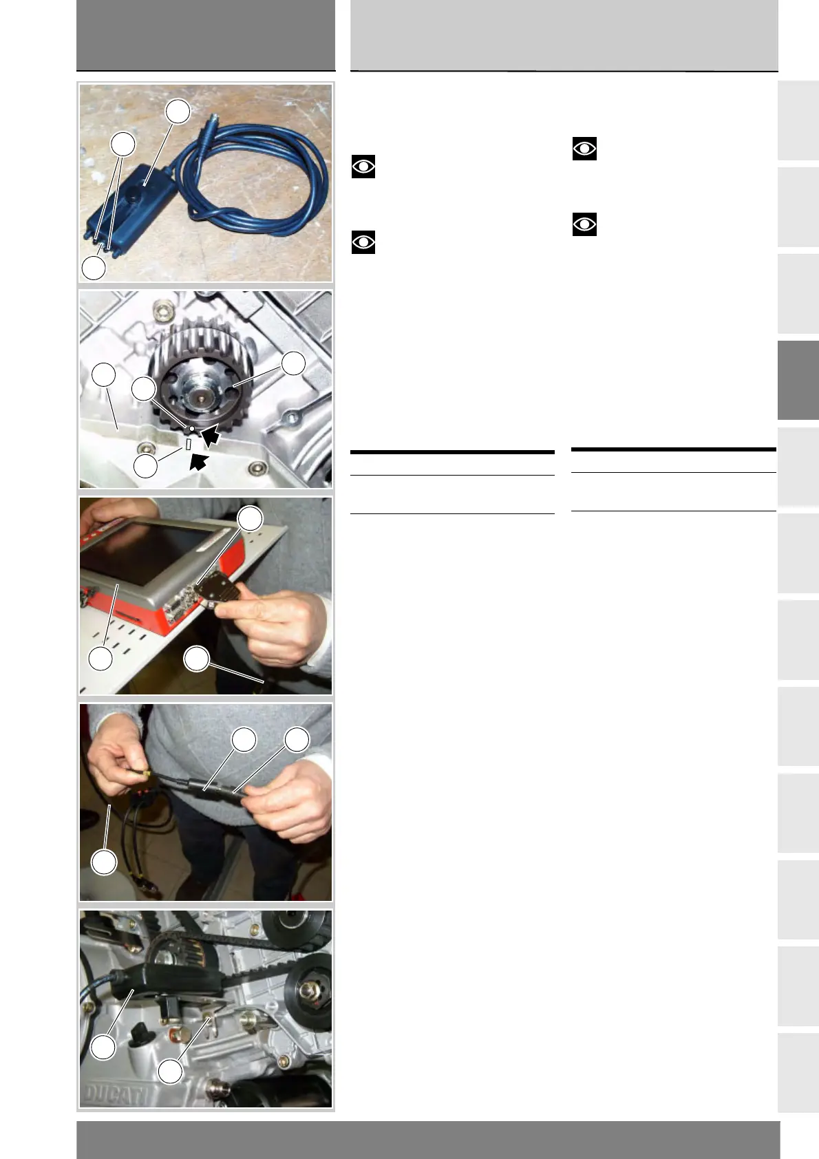
An optical reader is connected to
the DDS. The optical reader has a
green LED that serves to determine
correct positioning in front of the
belt to be tested. It is also equipped
with an infrared transmitter (A) and
receiver (B) designed to detect
oscillations of a belt when caused
to vibrate with the flick of a finger.
Remove the spark plugs
Position the crankshaft in such a
way that the horizontal cylinder piston
is at TDC of the power stroke.
This is achieved by aligning timing
mark (C) on intermediate timing
pulley (19) with reference notch (D)
on the clutch cover (20).
Switch on the DDS tester (1); see
heading “Tester Power Supply”.
Connect the power and disgnostics
cable (Measurement Module) (3) to
the measurement module connector
(F) on the DDS tester (1).
Connect the belt tension sensor (15)
to the connector (V) of the power and
diagnostics cable (Measurement
Module) (3).
Secure the mounting bracket of the
belt tension sensor(15) using the
timing belt cover screw (21).
Aim the central green LED of the
sensor (15) at the mid-point of the
belt section, with the reader parallel
to the belt and at a distance of
about 1 to 1.5 cm from it.
Operation See Sect.
Remove the RH side
fairing
E 2
Remove the cylinder
head side covers
N 4.2
Controllo e registrazione
tensione cinghie
distribuzione
Note
I simboli delle icone utilizzate
nella procedura sono riportati in una
tabella alla fine della presente sezione.
Note
L'operazione, effettuata con
l'ausilio del DDS, ha il vantaggio di
poter essere seguita su entrambe le
cinghie con il motore montato sul
telaio. Al DDS va collegato un lettore
ottico. Questo ha un led verde che
serve per effettuare il suo corretto
posizionamento davanti alla cinghia.
Possiede inoltre un emettitore (A) e
un ricevitore (B) infrarosso, capaci
di rilevare le oscillazioni della cinghia
opportunamente sollecitata con un
dito.
Rimuovere le candele.
Posizionare l'albero motore in modo
che il cilindro orizzontale abbia il
pistone al punto morto superiore in
fase di scoppio.
Ciò si ottiene allienando il segno di
fase (C) sulla puleggia (19) del
rinvio distribuzione con la tacca di
riferimento (D) sul coperchio
frizione (20).
Accendere lo strumento DDS (1)
facendo riferimento al paragrafo
“Alimentazione dello strumento”.
Collegare il cavo alimentazione e
diagnosi (Modulo Misure) (3) al
connettore modulo misure (F)
dello strumento DDS (1).
Collegare il sensore tensionamento
cinghie (15) alla presa (V) del cavo
alimentazione e diagnosi (Modulo
Misure) (3).
Fissare la staffa del supporto del
sensore tensionamento cinghie (15)
utilizzando la vite (21) di fissaggio
del coperchio copricinghia.
Direzionare il led verde centrale del
sensore (15) verso la parte centrale
del ramo della cinghia, posizionando
il sensore (15) in asse rispetto alla
cinghia ed a una distanza di circa
1÷1,5 cm.
Operazioni Rif. Sez.
Rimuovere la carena
laterale destra
E 2
Rimuovere le cartelle
laterali
N 4.2
B
A
15
C
D
20
19
F
1 3
V
3
15
21
15