A
B
C
D
E
F
G
H
L
M
N
P
Motore
Engine
sezione / section
N 6.3
123 749/749 DARK/749S - M.Y. 2005 - edizione/edition 00
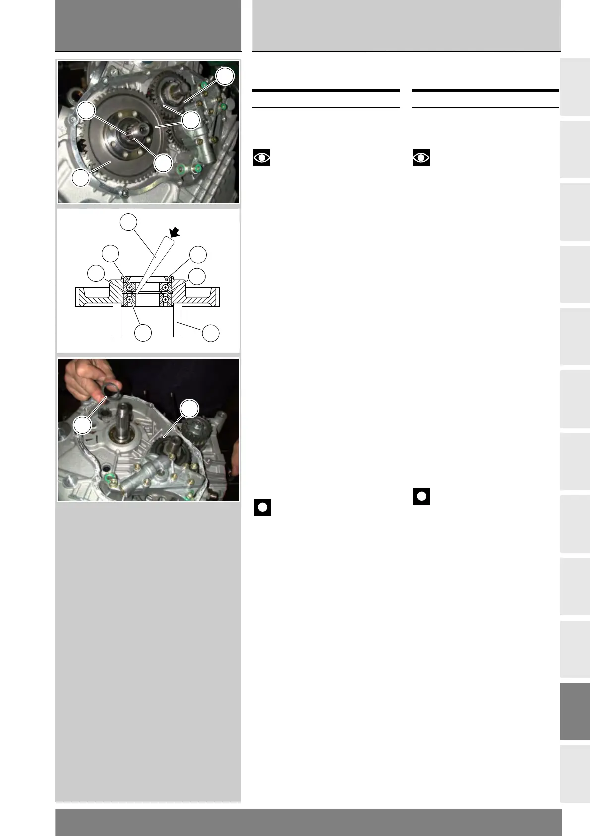
Smontaggio coppia
primaria
Note
Per una migliore chiarezza le
immagini rappresentano un motore
rimosso dal telaio.
Sfilare dall’albero primario cambio il
distanziale (8) e l’anello OR (1) in
appoggio sul cuscinetto (6)
dell’ingranaggio condotto (C)
trasmissione primaria (3).
Sfilare l'ingranaggio condotto (C) della
primaria (3) completo di cuscinetti e
anello di tenuta.
Per la sostituzione degli elementi
interni dell'ingranaggio è necessario
disporre di un punzone (A) e di una
base di appoggio (B) appropriati.
Dopo aver rimosso l'anello di tenuta (2),
battere dall'interno verso l'esterno
utilizzando come appoggio una parte
dell'anello interno del cuscinetto (4)
da rimuovere, dopo aver scostato il
distanziale (5) posto tra i due cuscinetti.
Cambiare sempre punto di appoggio
per ottenere un'estrazione lineare.
Procedere nello stesso modo per
rimuovere il cuscinetto (6).
Importante
Una volta rimossi sostituire
sempre; l'anello di tenuta (2),
l'anello seeger speciale (12) e il
distanziale (5). Questi ultimi due
particolari vanno sempre sostituiti
in coppia.
Sfilare il distanziale (7) dall'albero
primario del cambio.
Rimuovere la pompa olio (Sez. N 2.3)
per poter rimuovere l’ingranaggio
conduttore (D).
Operazioni Rif. Sez.
Rimuovere il coperchio
frizione
N 6.2
Removing the primary
drive gears
Notes
For clarity purposes, the figures
show the engine removed from the
frame.
Extract from the primary drive shaft
the spacer (8) and O-ring (1) resting
against the bearing (6) of the driven
gear (C) of the primary drive (3).
Extract the driven gear (C) of the
primary drive (3) complete with
bearing and seal ring.
Replace gear inner parts with the aid
of a suitable drift (A) and a bearing
surface (B).
After having removed the seal
ring (2), tap from the interior to the
exterior using part of the inner race
of the bearing (4) to be removed as
a rest, after having moved aside the
spacer (5) located between the two
bearings.
Tap on different supporting points
for linear removal.
Use the same technique to remove
the bearing (6).
Important
Once removed always replace:
the seal ring (2), special circlip (12)
and spacer (5). These latter two
components should always be
replaced together.
Remove spacer (7) from the primary
gearbox shaft.
Remove the oil pump (Sect. N 2.3)
so as to be able to remove the driving
gear (D).
Operation See Sect.
Remove the clutch
cover
N 6.2
1
C
8
3
D
12
B
4
5
2
A
6
D
7