A
B
C
D
E
F
G
H
L
M
N
P
Motore
Engine
sezione / section
N 4.1
53 749/749 DARK/749S Aggiornamento/Update - M.Y. 2006 - edizione/edition 00
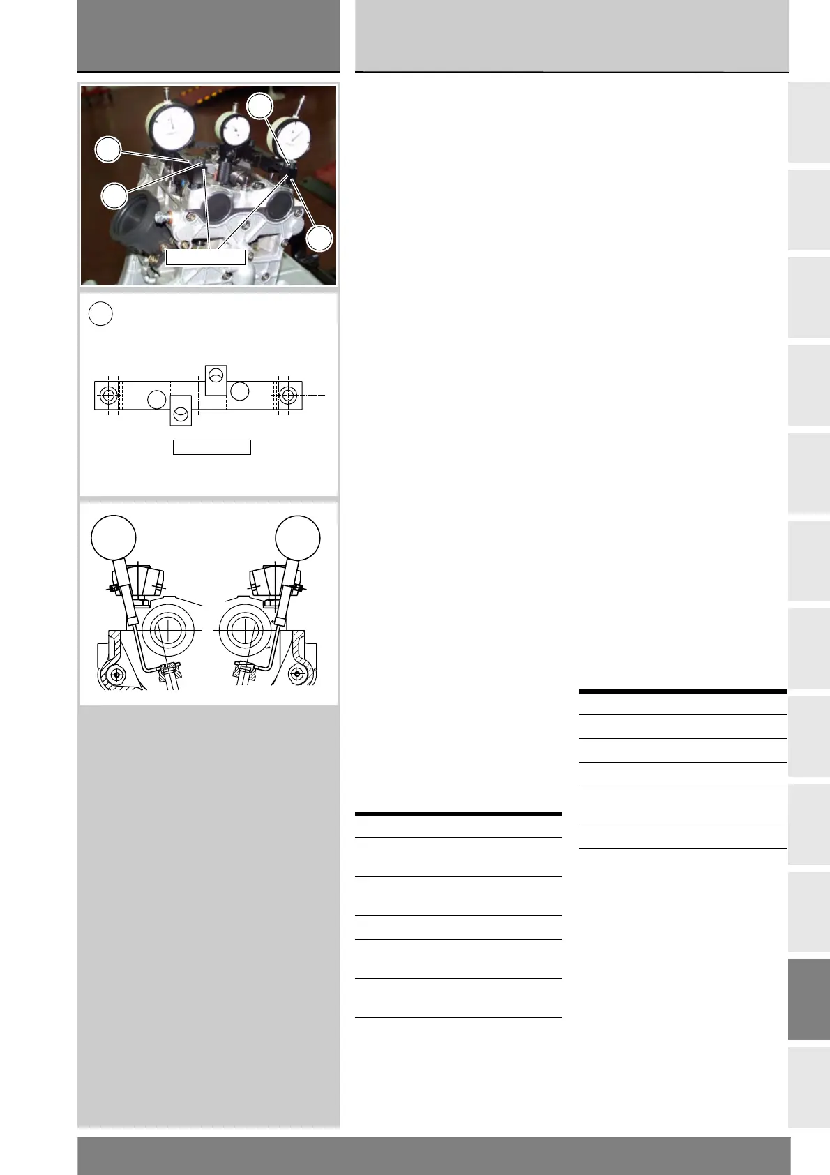
Verifica alzata valvole
Portare il motore nella configurazione
descritta per la “Verifica e
registrazione gioco valvole”,
precedentemente riportata.
Installare il supporto (D) del
comparatore 88765.1181 sulle
colonnette dei supporti alberi
distribuzione, lato aspirazione e
bloccarlo con i pomelli (C).
Con alberi distribuzione in posizione
di riposo, azzerare il gioco valvola in
apertura inserendo la lama di uno
spessimetro, di spessore adeguato,
tra bilanciere superiore e registro di
apertura.
Bloccare il comparatore nella sede
del supporto con la segnatura “A” e
posizionare il tastatore a forcella in
appoggio sulla superficie del registro
di chiusura.
Azzerare il comparatore sulla
posizione di valvola chiusa.
Ruotare l’albero distribuzione di
aspirazione facendo compiere una
alzata completa alle valvole di
aspirazione.
Verificare sul comparatore del calibro
che il valore rilevato corrisponda a
quello prescritto (Sez. C 1.1).
Eseguire la stessa operazione per le
valvole di scarico, spostando il
supporto sulle colonnette opposte e
posizionando il comparatore nella sede
del supporto (D) con la segnatura “S”.
Procedere al rimontaggio eseguendo le
stesse operazioni riportate al paragrafo
“Verifica e registrazione gioco valvole”,
precedentemente riportata.
Procedere al rimontaggio dei
componenti rimossi per le
operazioni descritte.
Operazioni Rif. Sez.
Rimontare le cinghie
distribuzione
N 4.2
Rimontare il coperchio
testa
N 4.4
Rimontare l’airbox L 6
Rimontare il gruppo
codone-serbatoio benzina
E 3
Rimontare il radiatore
acqua
N 3.2
Rimontare le carenature
laterali
E 2
Checking valve lift
Put the engine in the condition
described in “Checking and adjusting
valve clearance” above.
Install the dial gauge support (D)
88765.1181 on the intake side
camshaft bearing studs, and lock
it with the knobs (C).
Reset the opening valve clearance
when the camshaft is in its rest
position by fitting a feeler gauge
between the upper rocker arm and
opening shim.
Lock the dial gauge into the seat of
the support marked “A” and position
the fork against the face of the
closing shim.
Set the dial gauge to zero when the
valve is fully closed.
Rotate the intake camshaft so as to
allow the intake valves lift fully.
Check that the reading on the dial
gauge corresponds to the specified
value (Sect. C 1.1).
Repeat the same procedure with the
exhaust valves, moving the support
to the opposite studs and fitting the
dial gauge into the seat marked “S”
on the support (D).
Refit all parts by carrying out the
operations described under “Checking
and adjusting valve clearance” above.
Refit all the components removed in
the procedure.
Operation See Sect.
Refit the timing belts N 4.2
Refit the rocker cover N 4.4
Refit the airbox L 6
Refit the fuel tank/tail
guard assembly
E 3
Refit the radiator N 3.2
Refit the side fairings E 2
88765.1181
D
C
C
D
A
S
88765.1181
D