A
B
C
D
E
F
G
H
L
M
N
P
Uso e manutenzione
Use and Maintenance operations
sezione / section
D 4
21 749/749 DARK/749S Aggiornamento/Update - M.Y. 2006 - edizione/edition 00
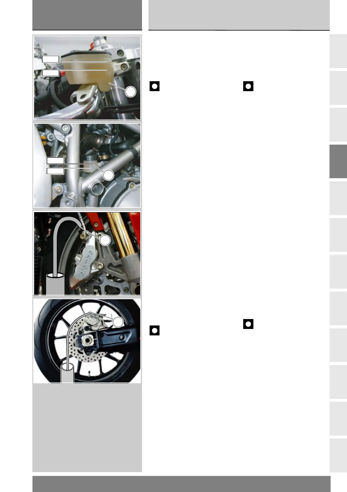
Riempimento circuito
impianto frenante
Riempire i serbatoi (A) o (B) con
olio prescritto prelevato da un
contenitore intatto.
Importante
Mantenere sempre a livello
l’olio dell’impianto durante tutta
l’operazione e lasciare l’estremità
del tubo trasparente sempre
immersa nel liquido scaricato.
Azionare diverse volte la leva o il
pedale del freno per riempire
l’impianto e spurgare l’aria. Collegare
alla valvola di spurgo lo spurgatore.
Pompare con lo spurgatore e allentare
la valvola di spurgo (3) o (5)
verificando sempre che il livello non
scenda al di sotto del MIN.
Ripetere quest’ultima fase fino a
quando, nel tubo trasparente
collegato alla valvola di spurgo,
non appaiono più bolle d’aria.
Bloccare la valvola di spurgo (3) o (5)
alla coppia prescritta (Sez. C 3).
In caso di indisponibilità dello
spurgatore collegare alla valvola
di spurgo (3) o (5) un tubicino in
plastica trasparente come descritto
per lo scarico dell’impianto. Aprire la
valvola di spurgo (3) o (5) di 1/4 di
giro e azionare la leva o il pedale
del freno fino a quando inizierà ad
uscire fluido dalla valvola di spurgo.
Tirare completamente la leva o il
pedale e poi allentare la valvola di
spurgo di almeno 1/4 di giro.
Attendere qualche secondo; rilasciare
lentamente la leva o il pedale e
chiudere contemporaneamente la
valvola di spurgo (3) o (5).
Importante
Non rilasciare la leva o il pedale
del freno se la valvola non è ben serrata.
Fill the brake system
with fluid
Fill the reservoir (A) or ((B) with the
recommended fluid taken from a
previously unopened container.
Important
During the operation, the fluid
level must remain topped up at all
times. The end of the transparent
plastic tubing must remain immersed
in the discharged fluid at all times.
Operate the brake lever (or pedal)
several times to allow the fluid to
reach all points of the circuit and
expel any air. Connect the bleeding
tool to the bleed valve.
Pump with the bleeder and loosen
off the bleed valve (3) or (5). Check
that the reservoir level does not fall
below the MIN mark.
Repeat the bleeding operation until
the fluid flowing from the tube is
completely free of air bubbles.
Tighten screw (3) or(5) to the
specified torque (Sect. C 3).
If you do not have a brake bleeding
tool available, connect a length of
transparent plastic tubing to the bleed
valve (3) or (5) as described in the
draining procedure. Open the bleed
valve (3) or (5) by a 1/4 turn and
operate the brake lever (or pedal)
several times until the fluid starts
coming out of the bleed valve. Pull
the lever fully in and loosen off the
bleed valve by at least a 1/4 of a turn.
Wait a few seconds and then
release the lever gradually, while
simultaneously closing bleed valve (3)
or (5).
Important
Do not release the brake
lever (or pedal) until the bleed valve
has been fully tightened.
MAX
MIN
A
MAX
MIN
B
3
5