A
B
C
D
E
F
G
H
L
M
N
P
Impianto elettrico
Electric system
sezione / section
P 6
54 749/749 DARK/749S - M.Y. 2005 - edizione/edition 00
6 - DISPOSITIVI DI
SICUREZZA E
PROTEZIONE
Controllo componenti
Commutatore a chiave
Scollegare il commutatore a chiave (A)
dall'impianto elettrico aprendo la
sua connessione (vedi capitolo
“Disposizione dei cablaggi sul
motociclo” di questa sezione) e
verificare con un multimetro la
continuità dei collegamenti interni
operando come segue:
girare la chiave di accensione sulla
posizione OFF e collegare un
multimetro (Sez. P9) ai contatti (1) e (4)
per verificare la continuità elettrica.
La resistenza indicata dallo strumento
deve essere prossima allo zero e,
se presente, deve essere emesso
il segnale sonoro di continuità;
girare la chiave sulla posizione ON e
collegare un multimetro ai contatti (3)
e (6) e poi a quelli (2) e (5) per
verificare la continuità elettrica.
La resistenza indicata dallo strumento
deve essere prossima allo zero e,
se presente, deve essere emesso
il segnale sonoro di continuità;
portare la chiave su PARK e collegare
un multimetro ai contatti (1) e (4) e
poi a quelli (3) e (5) per verificare la
continuità elettrica. La resistenza
indicata dallo strumento deve essere
prossima allo zero e, se presente,
deve essere emesso il segnale
sonoro di continuità;
portare la chiave su LOCK e collegare
un multimetro ai contatti (1) e (4)
per verificare la continuità elettrica.
La resistenza indicata dallo strumento
deve essere prossima allo zero e,
se presente, deve essere emesso il
segnale sonoro di continuità.
6 - SAFETY AND
PROTECTIVE DEVICES
Checking components
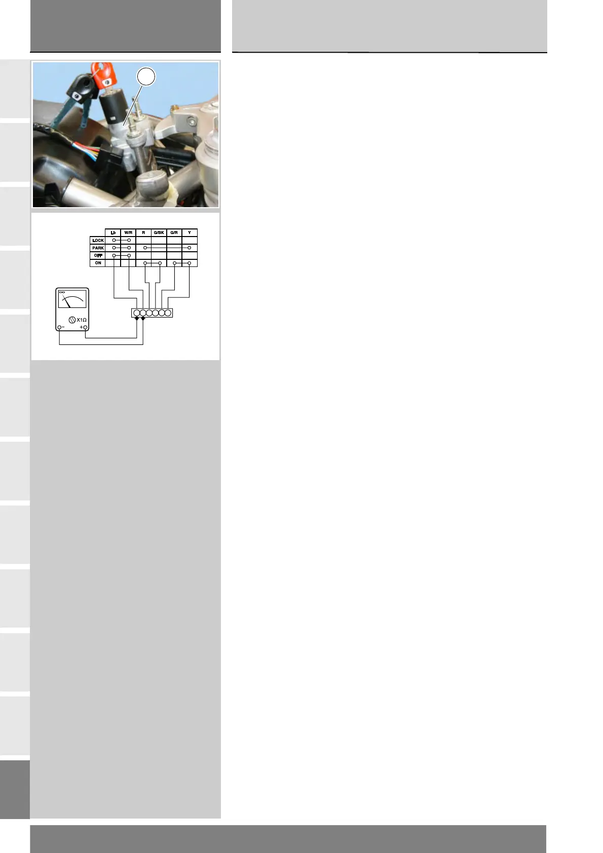
Ignition switch
Disconnect the ignition switch (A)
from the wiring harness by opening
its connector (see “Wiring harness
layout” in this section) and use a
multimeter to check its internal
connections as follows:
turn the ignition key to OFF and
connect a multimeter (Sect. P9) to
contacts (1) and (4) to check for
electrical continuity. The resistance
reading should be near zero and, if
present, the continuity sound signal
should be emitted.
turn the key to ON and connect the
multimeter to contacts (3) and (6) and
then (2) and (5) to check for electrical
continuity. The resistance reading
should be near zero and, if present,
the continuity sound signal should be
emitted.
turn the key to PARK and connect the
multimeter to contacts (1) and (4) and
then (3) and (5) to check for electrical
continuity. The resistance reading
should be near zero and, if present,
the continuity sound signal should be
emitted.
turn the key to LOCK and connect the
multimeter to contacts (1) and (4)
to check for electrical continuity.
The resistance reading should be near
zero and, if present, the continuity
sound signal should be emitted.
A
1
4
3
6
2
5
P