A
B
C
D
E
F
G
H
L
M
N
P
Impianto elettrico
Electric system
sezione / section
P 4
39 749/749 DARK/749S Aggiornamento/Update - M.Y. 2006 - edizione/edition 00
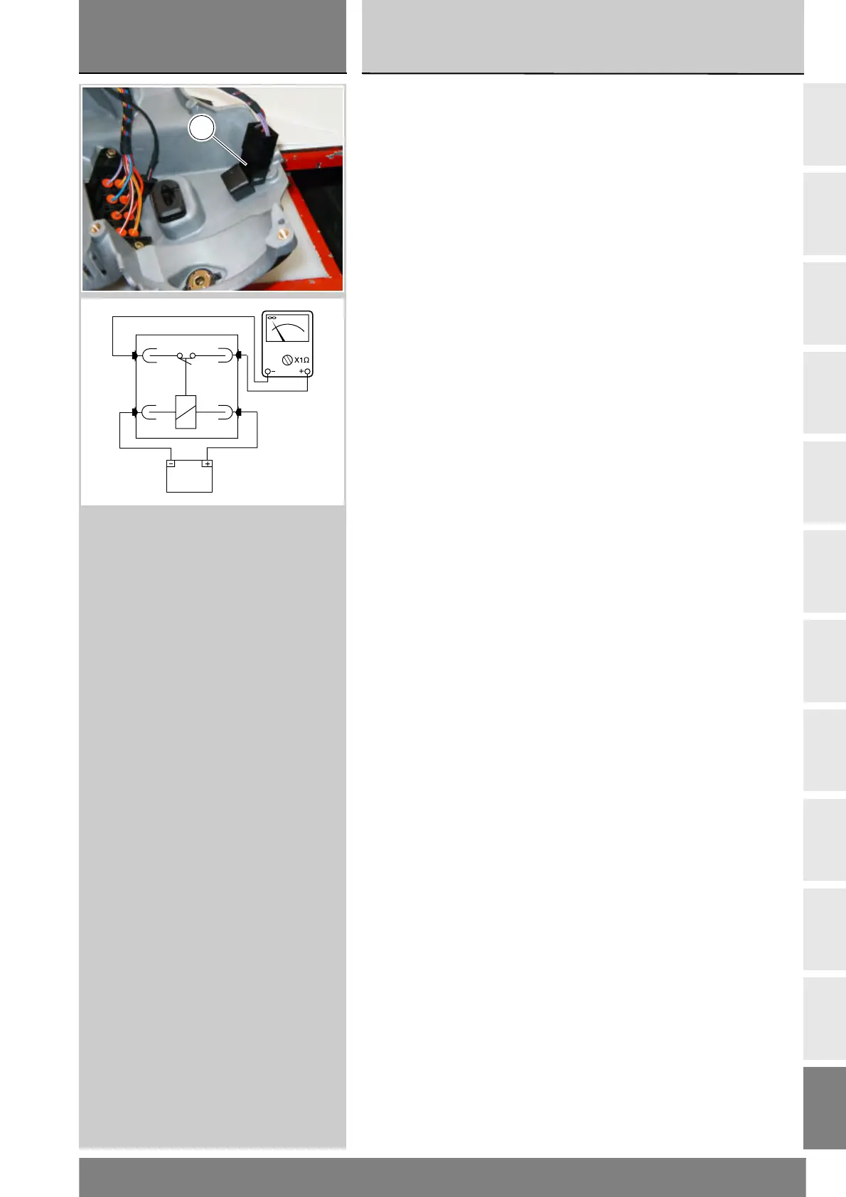
High beam lights relay
This is installed inside the headlight
assembly.
To access this relay you need to
remove the headlight assembly
(Sect. H 6) and opene it as
described in this section.
The high beam relay (1) has been
added to the electrical circuit to enable
the lights power down strategy.
This strategy is as follows:
1 If the lights are switched on,
they automatically switch off
when the engine is started.
2 If the lights are switched on, they
will switch off automatically after
60 seconds from the time of key
ON if the engine remains stopped.
If this strategy is not performed,
check the correct operation of the
various parts involved.
Checking operation of the high
beam lights relay
Disconnect the relay from the electrical
system and apply 12V (battery voltage)
between contacts (86) and (85)
(small contacts): you should hear a
click that confirms that the internal
electromagnet has switched.
Connect a multimeter to contacts (30)
and (87) (big contacts) to test for
electrical continuity (Sect. P9).The
resistance readingon the multimenter
should be near zero and the audible
continuity signal should sound (on
multimeters equipped with this
function). If this does not occur,
the part must be replaced.
Relè luci abbaglianti
E' posizionato all'interno del gruppo
ottico.
Per avere accesso a questo
componente è necessario rimuovere
il gruppo ottico (Sez. H 6) ed aprirlo
come descritto in questa sezione.
Il relè luci abbaglianti (1) è stato
introdotto nell'impianto per poter
eseguire la strategia di spegnimento
luci che consiste:
1 Le luci se accese si spengono
simultaneamente all'atto
dell'avviamento veicolo.
2 Le luci se accese si spengono se
dopo 60 secondi da chiave ON
con motore spento.
In caso di non funzionamento di
questa strategia verificare il
corretto funzionamento.
Controllo funzionalità relè luci
abbaglianti
Scollegare il relè dall'impianto
elettrico e applicare una tensione di
12V (batteria) tra i contatti (86) e (85)
(contatti piccoli): si deve sentire uno
scatto che indica il funzionamento
dell'elettrocalamita interna.
Collegare un multimetro ai contatti (30)
e (87) (contatti grandi) per verificare
la continuità elettrica (Sez. P9).La
resistenza indicata dallo strumento
deve essere prossima allo zero e, se
presente, deve essere emesso il
segnale sonoro di continuità. Se ciò
non si verifica sostituire l'elemento.
1
12V
85
30 87
86