A
B
C
D
E
F
G
H
L
M
N
P
Motore
Engine
sezione / section
N 4.5
85 749/749 DARK/749S - M.Y. 2005 - edizione/edition 00
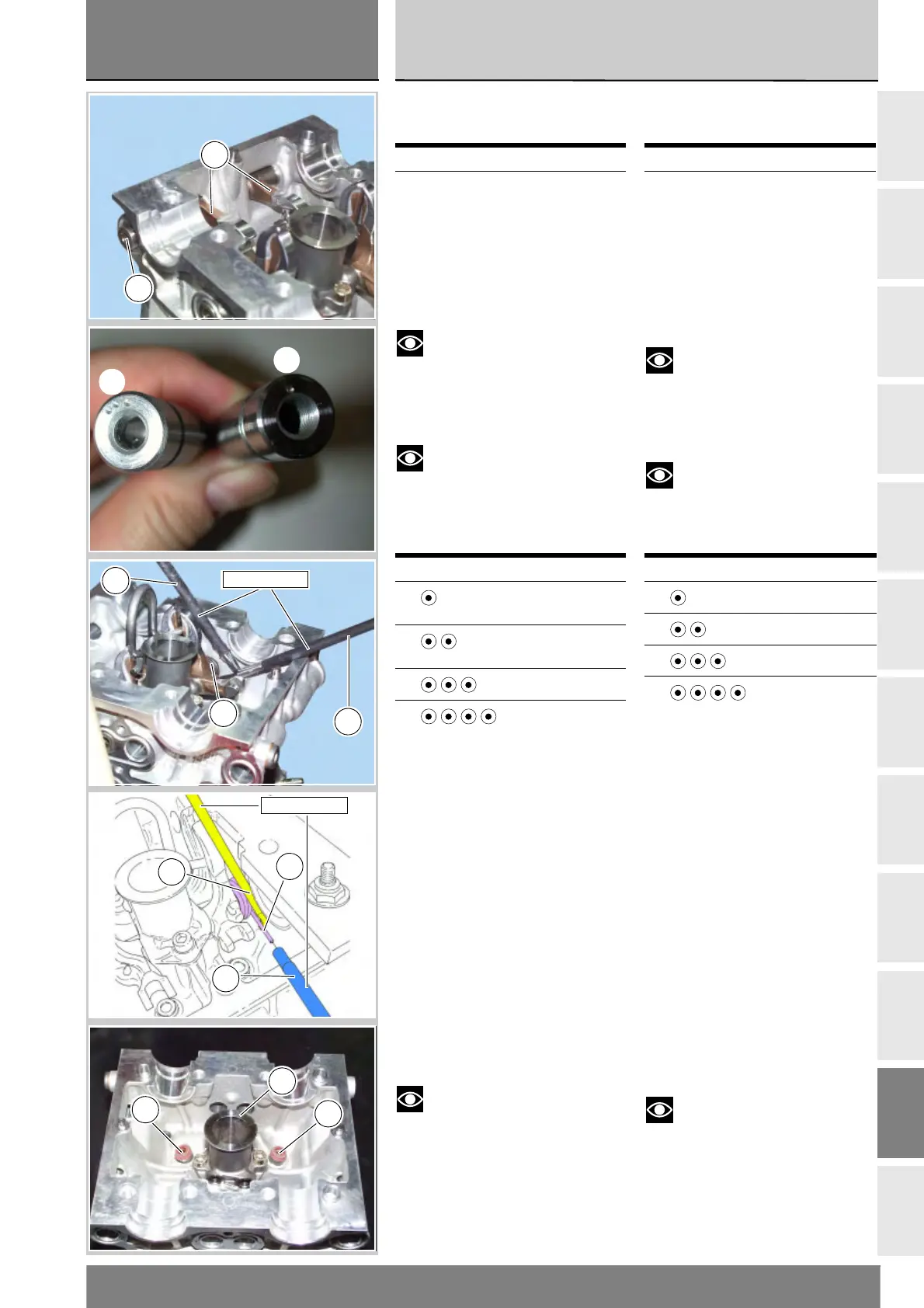
Removing the valve
rocker arms
With the head in the configuration of
the previous paragraph, remove the
rocker arms.
Use the extractor 88713.1994 to
slide off the shafts (2) and (17) of the
opening rocker arms (3) on the intake
and exhaust sides.
Notes
The preceding operations are
not required to remove the intake
rocker arms.
Remove the opening rocker arms (3).
Notes
The rocker arm shafts are
numbered or punched in pairs on their
outer faces to indicate the installation
order, starting from the intake side.
Using accessory (C) of the rocker arm
spring tensioning kit 88713.2069
installed between the spring and the
inner wall of the head, move the
straight end of the rocker arm return
spring (19) and (18) and fit it into the
bored shaft (D). Use the shaft to slide
the end of the spring into its final
position.
Use the extractor 88713.1994 again
to slide off the shafts (1) and (15) of
the closing rocker arms on the intake
and exhaust sides.
Remove the closing rocker arms (4)
and (16) and the springs (19) and (18).
Remove the seal rings (8) from the
ends of the valve guides.
The head is fitted with the sparkplug
cap (27) which acts as an internal
support for the closing rocker arm
shafts.
Notes
Do not under any circumstances
remove the sparkplug cap.
Replacement heads are supplied
already equipped with this item.
Repeat the same procedure for the
other head.
Operation See Sect.
Removing the valves N 4.5
Punching Rocker arm shaft
(1)
Opening/intake
(2)
Closing/intake
(3)
Closing/exhaust
(4)
Opening/exhaust
Smontaggio bilanceri
valvole
Con la testa nelle condizioni riportate
al paragrafo precedente, procedere
alla rimozione dei bilanceri.
Con l’estrattore 88713.1994 sfilare
i perni (2) e (17) dei bilanceri
apertura (3) lato scarico e aspirazione.
Note
Lo smontaggio dei bilancieri di
aspirazione non implica le operazioni
precedenti.
Rimuovere i bilanceri di apertura (3).
Note
I perni dei bilanceri sono
numerati o punzonati a coppie sulla
faccia esterna secondo l'ordine di
montaggio con partenza dal lato
aspirazione.
Utilizzando l’arpione (C) del kit
tensionamento molle bilanceri
88713.2069, posizionato fra la molla e
la parete interna della testa, scostare
l'estremità rettilinea della molla (19)
e(18) ritorno bilanceri e infilarla
nell'asta forata (D). Usare l'asta per
accompagnare l'estremità della molla
fino ad una posizione di riposo.
Riutilizzando l’estrattore 88713.1994,
sfilare i perni (1) e (15) bilanceri
chiusura lato scarico e aspirazione.
Rimuovere i bilanceri di chiusura (4)
e(16) e le molle (19) e (18).
Rimuovere gli anelli di tenuta (8)
dalla estremità dei guidavalvole.
Sulla testa è montato il cannotto
candela (27) che funge da supporto
interno per i perni bilanceri di chiusura.
Note
Il cannotto candele non deve
mai essere scaricato.
In caso di sostituzione della testa,
questo viene fornito già assemblato
sulla testa.
Eseguire le stesse operazioni per
l'altra testa.
Operazioni Rif. Sez.
Smontaggio valvole N 4.5
Punzonatura Perno bilancere
(1)
Apertura/
Aspirazione
(2)
Chiusura/
Aspirazione
(3)
Chiusura/Scarico
(4)
Apertura/Scarico
17
3
(3)
(1)
19
88713.2069
C
D
88713.2069
19
C
D
27
8
8