A
B
C
D
E
F
G
H
L
M
N
P
Comandi - Dispositivi
Controls - Devices
sezione / section
F 4
21 749/749 DARK/749S Aggiornamento/Update - M.Y. 2006 - edizione/edition 00
Smontaggio comando
freno posteriore completo
Attenzione
La casa costruttrice della pompa
freno, considerando l’importanza in
termini di sicurezza che riveste questo
componente, suggerisce di non
intervenire in nessun modo all’interno
della pompa. Una revisione non
eseguita correttamente può mettere
in serio pericolo l’incolumità del
pilota e del passeggero.
Le operazioni di sostituzione si devono
limitare; alla leva di comando, al gruppo
serbatoio con relativi componenti di
fissaggio e al fissaggio pompa.
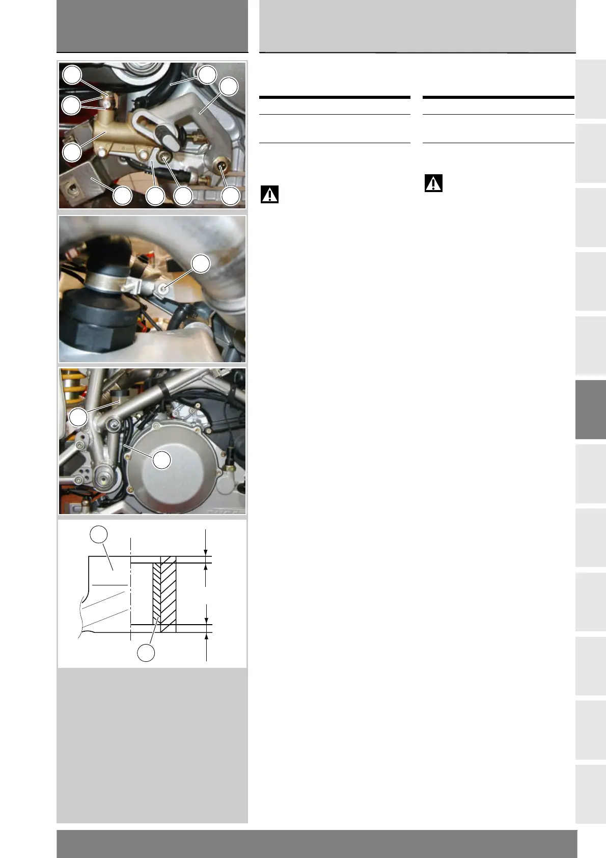
Svitare dalla pompa (16) la vite
speciale (22) e sfilare il tubo (28)
recuperando le guarnizioni (23).
Svitare la vite (2) di fissaggio staffa
supporto pompa (1) al motore, facendo
attenzione alla staffa di supporto
carena (A). Svitare la vite (9) di fissaggio
pedale (6) e staffa al motore.
Rimuovere il serbatoio olio (26)
completo di tubo (21) dal telaio
svitando la vite (31).
Rimuovere il comando freno
posteriore completo dal veicolo.
Scomposizione comando
freno posteriore
La pompa freno viene fornita
completa e non è possibile eseguire
sostituzione dei componenti interni.
Per la scomposizione dei componenti
esterni del gruppo pompa seguire le
indicazioni dell’esploso riportato a
inizio capitolo.
In caso di sostituzione della boccola (10)
interna al pedale freno (6), eseguire il
montaggio della boccola nuova
utilizzando per l’introduzione una
pressa e portandola alla quota di 2 mm
dalla faccia esterna del pedale.
Operazioni Rif. Sez.
Svuotare l’impianto
frenante
D 4
Rimuovere la carena
destra
E 2
Removing the complete
rear brake control
Warning
The brake master cylinder
manufacturer advises against
servicing the brake master cylinder
due to the safety critical nature of
this component. Incorrect overhaul of
this critical safety component can
endanger the rider and passenger.
Maintenance operations on these
units are limited to replacing the
following parts: control lever,
reservoir unit, reservoir fasteners
and master cylinder fasteners.
Undo the special screw (22) from
master cylinder (16) and withdraw
the pipe (28). Keep the seals (23).
Undo the screw (2) securing the
cylinder bracket (1) to the engine,
taking care not to damage the
fairing bracket (A). Undo the screw (9)
securing the pedal (6) and bracket
to the engine.
Remove the brake fluid reservoir (26)
complete with the pipe (21) from the
frame by undoing screw (31).
Remove the complete rear brake
control.
Disassembly of the rear
brake control
The brake master cylinder is
supplied only as a complete unit;
internal parts cannot be replaced.
To disassemble the external parts
of master cylinder assembly, refer
to the exploded view at the
beginning of this chapter.
If the bush (10) inside the brake
pedal (6) needs replacing, drive the
replacement bush into place using a
press. The bush must be seated
2 mm below the pedal's outer face.
Operation See Sect.
Drain the braking
system
D 4
Remove RH side fairing E 2
16
23
22
6
921
A
21
31
21
26
2 mm
2 mm
10
6